[Measurement (Scan Edge Position)]
This item can be changed if necessary. Usually, the factory default value can be used. After changing a setting, check whether measurement can be done properly by performing an actual measurement.
 Note
Note- In the "Item tab" area, tap [Measurement].
The edge profile of the measurement region is displayed in the "Image display" area.
- Set the value of each item in the "Display area" area.
You can set the "Display area No." by tapping the left or right button.
Table:
Measurement (Scan Edge Position) - Display Area
|
Set Value [Factory default]
|
|
|
|
Specify the part for which the edge profile is displayed. It should be a sequential number decided when the region was divided.
|
|
|
[As defined in the region settings]
|
Specify enabled/disabled for the displayed area. When [Enabled] is unchecked, measurement is not performed.
|
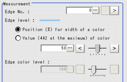
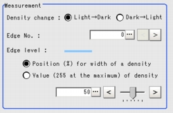
- Set the value of each item in the "Measurement" area.
[Edge No.] can be specified by tapping [<] and [>].
The values for [Edge level] and [Edge color level] can be adjusted by dragging the slider or by tapping the buttons at both ends of the slider.
Table:
Measurement (Scan Edge Position)
|
Set Value [Factory default]
|
|
|
|
Specify the number of the edge to be extracted.
Edge numbers are assigned to the detected edges, starting with 0 from the start point to the end point in the direction of the arrow of the measurement region.
|
|
- Position (%) for width of a color
- Value of color
|
|
|
|
Specify a level to remove colors other than the color specified in [Edge color] to enhance the edge color.
This option is enabled only when the [Edge color specification] is checked in [Edge color].
|
Table:
Measurement (Scan Edge Position)
|
Set Value [Factory default]
|
|
|
[Light  Dark]
Dark  Light
|
Select whether a black-to-white change or a white-to-black change should be recognized as a density change in the specified region.
|
|
|
Specify the number of the edge to be extracted.
Edge numbers are assigned to the detected edges, starting with 0 from the start point to the end point in the direction of the arrow of the measurement region.
|
|
- Position (%) for width of a density
- Value of density
|
|
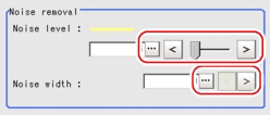
- Tap [...] of each item in the "Noise removal" area, and set values.
The value for [Noise level] can be adjusted by dragging the slider or by tapping the buttons at both ends of the slider.
The [Noise width] value can also be adjusted by tapping [<] and [>].
Table:
Measurement (Scan Edge Position) - Noise Removal
|
Set Value [Factory default]
|
|
|
|
Specify the noise level for judging the presence/absence of an edge.
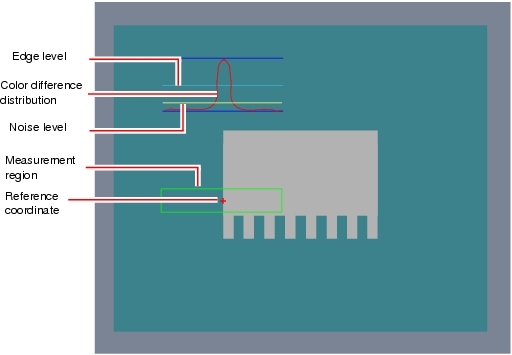
The maximum and minimum values of color differences in the edge detection region are obtained and, if the difference is lower than the noise level, no edges will be detected. If the detection is affected by noise, increase this value.
|
|
|
When there are two edges higher than the edge level and the distance between them is less than the noise width, these two edges are treated as noise. If the detection is affected by noise, increase this value.
|
- In the "Approximate line" area, specify the point to be used for the calculation for approximate lines.
Table:
Measurement (Scan Edge Position) - Approximate Line
|
Set Value [Factory default]
|
|
|
|
This item calculates an approximate straight line by excluding the points with large deviation among the measured points. The approximate straight line is calculated by using all the measured points.
|
 User's Manual, "Edge Measurement".
 User's Manual, "Inputting a Value"
 User's Manual, "Inputting a Value"The values for [Edge level] and [Edge color level] can be adjusted by dragging the slider or by tapping the buttons at both ends of the slider.
 User's Manual, "Inputting a Value"The value for [Noise level] can be adjusted by dragging the slider or by tapping the buttons at both ends of the slider.
 Setting Up [Scan Edge Position].


