Time Chart
When "Output control" Is Set to "None"
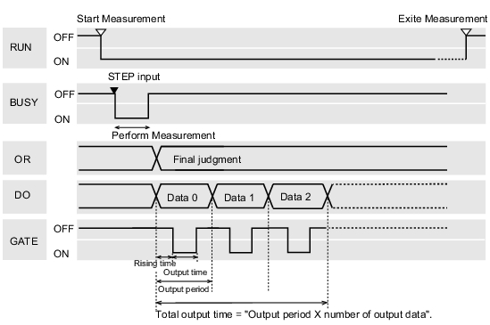
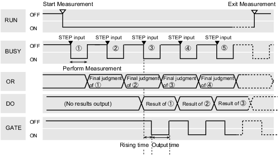
Output the measurement results if controller is not synchronous with external devices. After external devices detect GATE signal of controller, the measurement results are read during ON.
Input measurement trigger with in STEP signal range
Output Signal
Output Reflect in overall judgement result. When judgemnet results are either OK or NG, it's required to select ON or not in the setting window of communication specification. |
|
Output the Expression results set in Processing Item [Parallel Judgement Output]/[Parallel Data Out].
When judgemnet results are either OK or NG, it's required to select ON or not in the setting window of communication specification. |
|
Input Signal
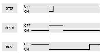
- READY signal can be changed below.
- Processing of ERROR signal when STEP signal is input during measurement
 Setting for Measurement
- Processing of ERROR signal when STEP signal is input during measurement
Important
- When parallel continuous measuring is engaged and continuous STEP signal is inputted, switching of scene group should be avoided. To switch a scene group, uncheck "Save scene group when switching" by either of the following methods.
- Using the Switch Scene Group window
 Switching the Scene Group
 - Using [Measure] - [Measure setting]
 Setting for Measurement
- Using the Switch Scene Group window
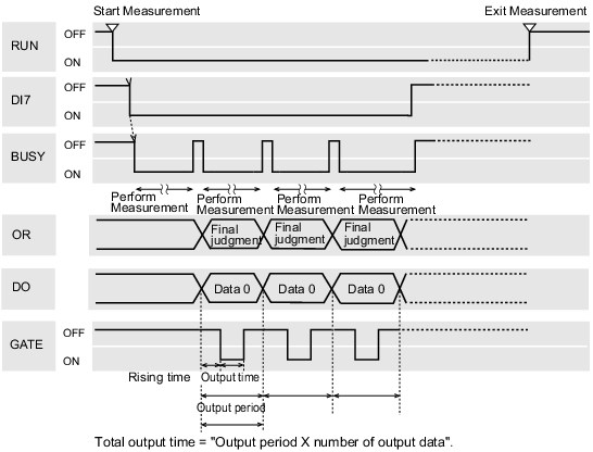
Continuous Measurement
Important
- Giving precedence to measurement when the input intervals of STEP signal is short, or while continuous measurement is being performed, display of measured results (overall judgment, image, judgment for each processing unit in the flow display, Detailed Results) may not be updated.
When the continuous End, the measurement results of the last time measurement will be viewed.
- Output functions the same as when "Output Control" is set to "None".
 When "Output control" Is Set to "None"
Input Signal
When "Output Control" Is Set to "Handshaking"
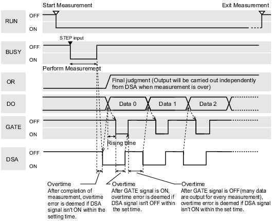
Output the measurement results if controller is synchronous with external devices. This function enables to effectively transfer data when many measurement results are output in sequence.
Input measurement trigger with in STEP signal range
- Output signal functions the same as when "Output Control" is set to "None".
 When "Output control" Is Set to "None"
Input Signal
When "Output Control" Is Set to "Synchronization output"
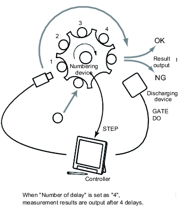
A method that enables processing time on the production line to Execute synchronously with result output time of controller. After STEP signal of "Number of delay" in communication specification is ON, measurement results will be output when STEP signal is ON next time.
- When "Output Control" of communication specification is set to "Synchronization output", the number of levels will be accumulated by ON times of STEP signal. So, it's advisable to set to one output for one measurement (1 unit for "Judgement Output", 1 data for "Data Output").
 Setting Communication Specifications (Parallel Interface)
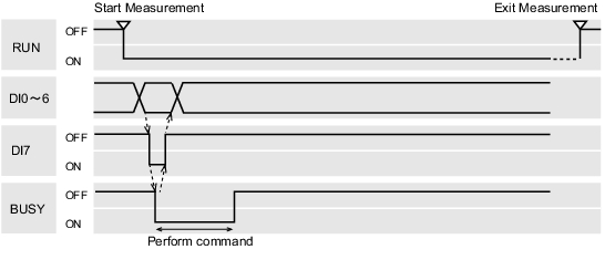
 - Only STEP signal is input for measurement command.
When serial command is used for measurement and continuous measurement, output time will mismatch, and the controller will lead to mis-operation.
Input measurement trigger with in STEP signal range
- Output functions the same as when "Output Control" is set to "None".
 When "Output control" Is Set to "None"
Scene/Scene Group Switch
Output Signal
Turns ON when the controller is available for measurement and the Operation window is displayed. It is OFF with the Adjustment window, so switch to the Operation window during operation. |
|
