I/O Format (Parallel Interface)
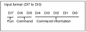
Input Format
Important
- When parallel continuous measuring is engaged and continuous STEP signal is inputted, switching of scene group should be avoided. To switch a scene group, uncheck "Save scene group when switching" by either of the following methods.
- The Switch Scene Group window
 Switching the Scene Group
 - [Measure setting] in the [Measure] menu
 Setting for Measurement
- The Switch Scene Group window
Output Format
Output the measurement results whenever performing measurement. The result is output only if "Output" of [Test Measurement setting] in the "Control" area is checked.
 Setting for Measurement
When judgemnet results are either OK or NG, it's possible to choose output ON. Ex-factory setting is "ON if NG".
 Setting Communication Specifications (Parallel Interface)
When judgemnet results are either OK or NG, it's possible to choose output ON. Ex-factory setting is "ON if NG".
The results of Judge 0 to 15 set in [Parallel Judgement Output] are output to DO 0 to 15. |
|
Value of Data 0 to 7 in [Parallel Data Out] are output in 16-digits format.
|
- After measurement, the data output to OR signal or DO signal shall be kept until next measurement. Please note, output state shall be maintained even if measurement is finished.
When the Output "One-shot OR signal" Setting Communication Specifications (Parallel Interface) is set to ON, however, the OR signal, after the set output time has lapsed, will turn to OFF.
 - Ex-factory output is set OFF, and about 0.5s ON is maintained if switching-on. Due attention shall be paid to signal reading of external devices.

