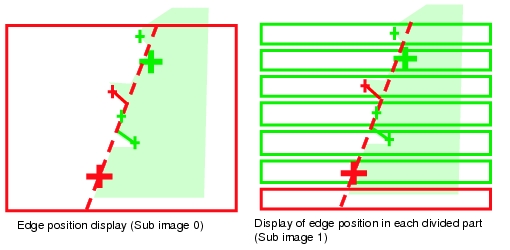
Points on Test Measurement and Adjustment (Scan Edge Position)
In addition to the camera input image, the measured region, a graphic display of the measured results, and the edge position (the cross-shaped cursor) are also displayed as results in the "Image Display" area.

Table:
Contents of Text (Scan Edge Position)
|
|
|
|
|
X-coordinate of the edge that is furthest from the start point of the measurement region
|
|
Y-coordinate of the edge that is furthest from the start point of the measurement region
|
|
X-coordinate of the edge that is closest from the start point of the measurement region
|
|
Y-coordinate of the edge that is closest from the start point of the measurement region
|
|
The average of X-coordinates of all the edges
|
|
The average of Y-coordinates of all the edges
|
|
The maximum distance between the approximate straight line and the edge position (plus direction)
|
|
The minimum distance between the approximate straight line and the edge position (minus direction)
|
|
Deviations in concavity and convexity
|
|
The straight line's inclination against the measurement region does not include 180, which is displayed as -180.
|
|
Number of parts for which the detection of edges have failed
|
Points on Adjustment
Select the adjustment method referring to the following points.
When the edge cannot be detected satisfactorily
- Set up the options in [Measurement].
- Specify the edge color in [Edge color].
When noise is detected as an edge
- Specify a higher value for [Noise level] and [Noise width] in [Measurement].
 User's Manual, "Displaying Flow and Detail Result"