[Model (Fine matching)]
Register a fine image as the model. By matching this model with input images, unmatched parts will be detected as defects.
For the fine matching, the two pixels on the edge of the image cannot be registered as the model.
 Note
Note- The registering range will be lower if the images of measurement object are set with Filtering. When you set the image reading range using a camera with the partial scanning function, the range is also limited.
 Filtering
- In the "Item tab" area, tap [Model].
When setting a new model, you do not have to tap [Model].
- If necessary, set up the "Model parameter" area.
- Use the following Tools to specify the Model Registration range.
Table:
Drawing Tools Available for Model Registration (Fine Matching)
|
|
|
|
|
|
|
|
|
|
|
|
 Note
Note- If the model is an ellipse, its circumscribed rectangle is displayed as the search result of the model.
- In the "Figure setting" area, tap [OK].
Changing Model Parameters
This item can be changed if necessary. Usually, the factory default value can be used.
When any settings have been changed, verify whether measurements can be performed correctly through actual measurement.
- In the "Model parameter" area, specify a value for each item.
The "Boundary level" value can be adjusted by tapping [<] and [>].
Table:
Model (Fine Matching)
|
Set Value [Factory Default]
|
|
|
Selects the matching method for boundary areas where density changes.
|
|
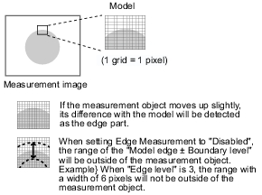
All areas are subject to the inspection, so that defects around boundaries can be detected. The edges similar to those in the model image are not regarded as defects. Check this option when inspecting defects around boundaries, such as chips and burrs.
|
|
Boundary areas are excluded from the inspection. Defects around boundaries are not to be detected.
"Boundary level" can be used to specify how many pixels around boundaries should be excluded from the inspection.
|
|
|
Specify the level to assimilate variations around boundaries where density changes.
Depending on the "Boundary inspection" value, the meaning is different.
|
 Filtering
 User's Manual, "Inputting a Value"
 Setting up [Fine matching].


