Conversion Method (Trapezoidal Correction+)
Set the input image conversion method.
- In the Item Tab area, tap [Conv. method].When making a new setting, you do not need to tap [Conv. method].
- As necessary, set the parameters.
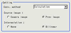 Setting itemSet value
[Factory default]DescriptionConv. method- 4 unit reference
- [Calculation]
Set the expression used for image conversion
4-unit reference: The parameters are set referencing the reference coordinates and measurement coordinates for the immediately preceding 4 units.
To set the reference position and measurement position with 4-unit reference, it is necessary to set the measurement position setting method to expression.To modify the expression for the reference position and measurement position set with 4-unit reference, select the Expression.Source image- Camera image
- [Prev image]
Set the image to be compensated.Interpolation- None
- [Bilinear]
Set the interpolation between pixels for image conversion.
To reduce conversion time more than raise compensation precision, set "None". - Set the reference position.
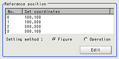 Setting itemSet value
[Factory default]DescriptionSetting method- [Figure]
- Operation
Set the method for setting the reference position.When fixed value is selected, specify the vertex position on the image.
After setting with an expression, if the setting is changed to a fixed value, the result of the expression is reflected as a fixed value.When Expression is chosenTap [Edit].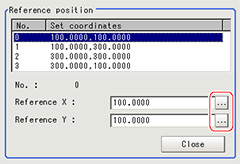 Tap [...] and set the expression.
 - Set the measurement position.
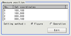 Setting itemSet value
[Factory default]DescriptionSetting method- [Figure]
- Operation
Set the method for setting the measurement position.
When fixed value is selected, specify the vertex position on the image.
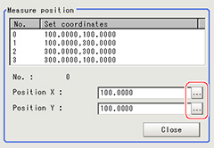
After setting with an expression, if the setting is changed to a fixed value, the result of the expression is reflected as a fixed value.When Expression is chosenTap [Edit].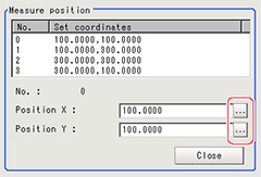 Tap [...] and set the expression.
 - Set the display settings as necessary.

Example of Setting
Here, the following two patterns for setting the reference position and measurement position are described.
Setting item | Pattern 1 | Pattern 2 |
Camera: Fixed tilt Work: No chatter  | Camera: Fixed vertical Work: Chatter 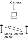 | |
Reference position | Figure | Figure |
Measurement position | Figure | Expression |
Pattern 1:
When the camera is installed tilted and there is no chatter in the work
 See the setting example for when there is no chatter in the work
Pattern 2:
When the camera is installed vertical and there is chatter in the work
 See the setting example for when there is chatter in the work.
Setting Example for when There Is No Chatter in the Work
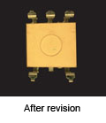
Even when there is a mechanical structure and the camera cannot be installed from the front, 4-point position information can be used to compensate for distortion in the image.
When you specify the four points used for distortion compensation and specify the positions where those four points should be as reference positions, the parameters for distortion compensation are set automatically.Each time a measurement is made, the distortion is automatically compensated for using these parameters.
When you specify the four points used for distortion compensation and specify the positions where those four points should be as reference positions, the parameters for distortion compensation are set automatically.Each time a measurement is made, the distortion is automatically compensated for using these parameters.
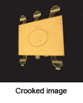
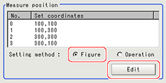
- Select "Figure" for the measurement position and tap Edit.
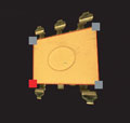
- Specify on the image which four points whose information to use for distortion compensation.
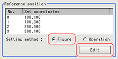
- Select "Figure" for the reference position and tap Edit.
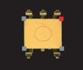
- On the image, specify which information for the positions where the four specified points should be to use for distortion compensation.When concrete coordinate positions are known or to measure them and find accurate positions, it is possible to set "Expression" and substitute measurement values from other processing units.
- Place a check at "Filtered image" in the display settings and check the image in which the distortion has been compensated for.

Setting Example for when There Is Chatter in the Work
Even when there is chatter in the work during transport and error is generated in the distance to the camera, 4-point position information can be used to compensate for distortion in the image.
Preset in other units so that when you specify the positions where the four points used for distortion compensation should be as reference positions, the 4-point position information can be acquired.Compensate for the distortion in the image so that the position information for the four points aligns with the reference positions when measurements are made. With this setting, 3D position deviation can be compensated for.
Preset in other units so that when you specify the positions where the four points used for distortion compensation should be as reference positions, the 4-point position information can be acquired.Compensate for the distortion in the image so that the position information for the four points aligns with the reference positions when measurements are made. With this setting, 3D position deviation can be compensated for.


- Select "Operation" for the measurement position and tap Edit.
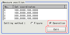
- Specify with the expression which four points to use the information of for compensation.Set the processing unit for acquiring the positions before the processing unit for trapezoidal distortion compensation.
- Select "Figure" for the reference position and tap Edit.

- On the image, specify which information for the positions where the four specified points should be to use for distortion compensation.When concrete coordinate positions are known or to measure them and find accurate positions, it is possible to set "Operation" and substitute measurement values from other processing units.

- Place a check at "Conversion image" in the display settings and check the image in which the distortion has been compensated for.
