Camera Settings (Camera Image Input)
Set the following photographing conditions for each camera.
 Note
Note- The displayed items differ depending on the camera type and lighting mode. Perform the following procedure as necessary in accordance with the use environment.
Camera Settings
Adjust the settings related to camera shutter speed and camera gain.
Select the shutter speed appropriate to the speed of the measurement object. Choose a faster shutter speed if the measurement object is moving quickly and the image is blurred.
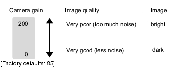
Adjust the camera gain when images cannot be brightened through the shutter speed, lens aperture, or lighting conditions. Usually, the factory default value can be used.
- In the Item Tab area, tap [Camera setting].
- In the "Camera settings" area, specify the shutter speed.
The setting methods are to select from the options offered or to set the value directly.
| Set value [Factory default] | |
|---|
| - [1/120]
(For FZ-SFx, FZ-SPx, FZ-SC2M/FZ-S2M, FZ-SC5M/FZ-S5M) - 1/200
- [1/500]
(for FZ-Sx, FZ-SLC, FZ-SZC) - 1/1000
- 1/2000
- 1/4000
- 1/8000
- 1/20000
- Set by number
1/10 to 1/50000
| Option values for the shutter speed differ depending on the camera type. |
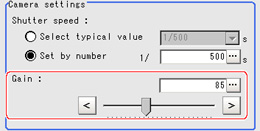
- Specify the camera gain while checking the image.
| Set value [Factory default] | |
|---|
| 0 to 230 [50] (For FZ-SFx, FZ-SPx, FZ-SC2M/FZ-S2M, FZ-SC5M/FZ-S5M) [85] (for FZ-Sx, FZ-SLC, FZ-SZC) | Adjust the camera gain when the shutter speed, the lens aperture, and lighting conditions cannot be used to brighten the image. Usually, the factory default value can be used. |
Frame/Field - for Monochrome Cameras Only
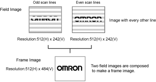
There are two methods to transfer one image from a camera to the controller: frame read and field read. Frame read is to read all of the scanned lines of the image. The result is called a frame image. Field read is used to read half of the interlaced scanned lines of the image. The result is called the field image.
Here, select the unit to be treated as one image.
- In the Item Tab area, tap [Camera setting].
- In the "Frame/Field" area, select either "Frame" or "Field".
| Set value [Factory default] | |
|---|
| | Measurements are done in frame units. |
| Measurements are done in field units. Select "Field" when you prefer shorter image input time rather than higher accuracy. Processing becomes faster since each image is scanned skipping one scan line per two consecutive lines, but the measurement precision is decreased because the vertical image resolution is lower. |
Number of lines to be read
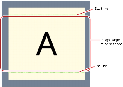
By narrowing the image range to be loaded, the image scan time can be shortened.
Set the range taking the offset of the measurement object into consideration.
The part of the image narrowed down by the start line and the end line will be displayed in the Image Display area of the processing item setting window or the Main screen.
 Note
NoteAbout minimum number of lines
- The minimum number of lines (minimum number of lines between start and end lines) is 12 lines.
- For 5 megapixel cameras, the end line is fixed to 1799.
- The coordinate values displayed as the measurement results are the values of the display position on the monitor.
- The coordinate values do not vary according to the settings for "Number of lines to be read".
- In the Item Tab area, tap [Camera setting].
- Set the start/end line in the "Number of lines to be read" area.
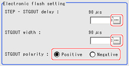
Electronic Flash Setting
This function is set when an electronic flash is used.This sets the output conditions for the signal for synchronizing the measurement and the electronic flash timing.
- In the Item Tab area, tap [Camera setting].
- In the "Electronic flash setting" area, specify each item.
| Set value [Factory default] | |
|---|
| | Set the waiting time from the time the STEP signal is input until the electronic flash trigger output signal comes ON. Delay Time=Count x 30μs + 90μs |
| 1 to 63 [3] (1 count 30μs) | Set the output time for the electronic flash trigger signal. |
| | Select the pulse polarity of the electronic flash trigger. Positive polarity: Flashes synchronized with the timing of the electronic flash trigger output signal changing from OFF to ON. Negative: Flashes when the strobe trigger output signal changes from ON to OFF. |
