[Measurement (Edge Position)]
Specify the range to be judged as OK.
 Note
Note- In the "Item tab" area, tap [Measurement].
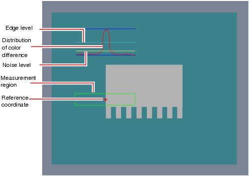
The edge profile of the measurement region (curve) is displayed in the "Image display" area.
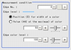
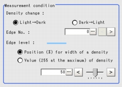
- If necessary, specify a value for each item in the "Measurement condition" area.
"Edge No." can be specified by tapping [<] and [>].
The values for "Edge level" and "Edge color level" can be adjusted by dragging the slider or by tapping the buttons at both ends of the slider.
Table:
Measurement (Edge Position)
|
Set Value [Factory Default]
|
|
|
|
Specify the number of the edge to be extracted.
Edge numbers are assigned to the detected edges, starting with 0 from the start point to the end point in the direction of the arrow of the measurement region.
|
|
- Position (%) for width of a color
- Value of color
|
|
|
|
Specify a level to remove colors other than the color specified in [Edge color] to enhance the edge color.
This option can be specified only if the [Edge color specification] is checked in [Edge color].
|
Table:
Measurement (Edge Position)
|
Set Value [Factory Default]
|
|
|
[Light  Dark]
Dark  Light
|
Select whether a black-to-white change or a white-to-black change should be recognized as a density change in the specified region.
|
|
|
Specify the code No. used to extract edge.
Code numbers are assigned to detected edges starting from 0 and going on in the direction from the start point (the arrow point) to the end point (the direction of arrow) in the selected area.
|
|
- Position (%) for width of a density
- Value of density
|
|
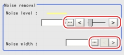
- If necessary, in the "Noise removal" area, tap [...] and specify a value for each item.
The value for "Noise level" can be adjusted by dragging the slider or by tapping the buttons at both ends of the slider.
The "Noise width" value can also be adjusted by tapping [<] and [>].
Table:
Measurement (Edge Position) - Noise Removal
|
Set Value [Factory Default]
|
|
|
|
This item used to judge the level of edge. Calculate the max and min chromatic aberrations of the detected areas in the edge. If the difference of the max and min chromatic aberrations is lower than the noise level, the edge will not exist. When the detection is affected by noise, increase the value.  User's Manual, "Noise Level" User's Manual, "Noise Level" |
|
|
Specify the width of noise.
Starting from the position where edges are initially detected and within the range of the noise width, the detected point will be regarded as noise if the chromatic aberration distribution is again lower than the Edge level. When the detection is affected by noise, increase the value.
|
- When the setting has been changed, tap [Measure] in the "Detail" area to verify whether measurements can be made correctly.
- In the "Judgement condition" area, tap [...] and input a value for each item.
 Note
Note- The values displayed in the individual fields are the measurement results of the displayed image. Take these values into consideration to determine the upper and lower limit values.
Table:
Measurement (Edge Position) - Judgement Condition
|
Set Value [Factory Default]
|
|
|
|
-99999.9999 to [99999.9999]
|
Specify the range of X-axis shifting that is judged to be OK.
|
|
[-99999.9999] to 99999.9999
|
|
|
-99999.9999 to [99999.9999]
|
Specify the range of Y-axis shifting that is judged to be OK.
|
|
[-99999.9999] to 99999.9999
|
Changing the Profile Display Setting
This item can be changed if necessary. Usually, the factory default value can be used.
To enlarge the graph along the vertical axis when the region is a circumference or arc, check the [Zoom] option and adjust the size by tapping one of the arrow buttons.
 User's Manual, "Edge Measurement".
 User's Manual, "Inputting a Value"The values for "Edge level" and "Edge color level" can be adjusted by dragging the slider or by tapping the buttons at both ends of the slider.
 User's Manual, "Inputting a Value"The value for "Noise level" can be adjusted by dragging the slider or by tapping the buttons at both ends of the slider.
 User's Manual, "Noise Level"
 User's Manual, "Inputting a Value"
 Note
Note Setting up [Edge Position].


