[3D Setting: 3D Coordinates (3D Camera Image Input)]
Adjust the coordinates between two cameras for 3D processing and set to convert measured value to actual dimensions. There are two ways to set the 3D coordinates. Select the method appropriate for the measurement environment (whether or not the measured object can be placed horizontally).
 Note
Note- When using an all-in-on camera, 3D coordinates are already set.
- Calibration target is used. Prepare it beforehand.
Measurement when the Measured Object can be Placed Horizontally
Specify "Position Z" and sample at two points with the calibration target placed far and near the camera. Set 3D coordinates by registering each position.
- Tap [3D setting] in the "Item tab" area (top) and tap [3D coordinates] in the "Item tab" area (bottom).
- Select the combination of cameras to be used in the "Set camera number" area.
- When using an all-in-one camera, uncheck "Availableness" of "The data camera has".
For an all-in-one camera, calibration is already set as factory default. Reset the calibration if the precision is insufficient.
 Note
Note- This item is displayed only when using an all-in-on camera.
- For an all-in-one camera, 3D coordinate setting parameters are provided as factory default.
When using an all-in-one camera, specify whether to use data inside the camera as 3D coordinate setting parameters.
Table:
3D Setting - 3D Coordinates (3D Camera Image Input)
|
Set Value [Factory Default]
|
|
|
When using an all-in-one camera, specify whether to use data inside the camera as 3D coordinate setting parameters.
|
|
|
|
The data inside the camera is used as 3D coordinate setting parameters.
|
|
The newly obtained data is used as 3D coordinate setting parameters.
|
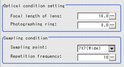
- Set the "Optical condition setting" and "Sampling condition" as necessary.
Table:
3D Setting - 3D Coordinates (3D Camera Image Input)
|
Set Value [Factory Default]
|
|
Optical condition setting
|
|
|
Set the focal length of the camera lens.
|
|
|
Set the photographing ring of the camera.
|
|
|
- 5 x 5
- 7 x 7
- 9 x 9
- 11 x 11
- [7 x 7 (Wide)]
- 9 x 9 (Wide)
|
Select the number of sampling points for sampling measurement. Unit is n points x n points.
Set up [3D coordinates] in the whole field of view. The correspondence between the field of view and sampling points are shown below: (Field of view: Sampling point) 35mm : 5 x 5 45mm : 7 x 7 55mm : 9 x 9 65mm : 11 x 11 75mm : 7 x 7 (Wide) 95mm : 9 x 9 (Wide)
|
|
|
Set the number of sampling measurements performed per surface.
Set [1] for environment with frequent vibrations.
|
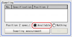
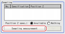
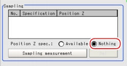
- Select "Available" for "position Z spec." in the "Sampling" area.
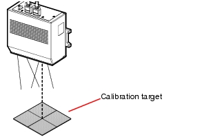
- Place the calibration target on the reference surface (0mm point).
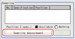
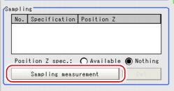
- Tap [Sampling measurement].
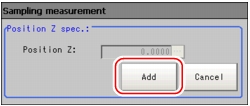
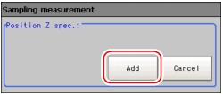
The Sampling Measurement window is displayed.
- Tap [Add].
The sampling result is displayed in [Sampling].
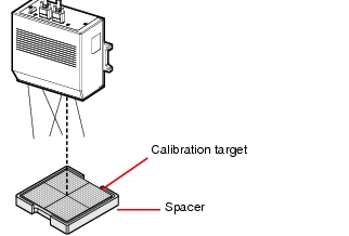
- Set the calibration target in the spacer.
 Note
Note- The height will be 10mm when the calibration target is set on the concaved side of the spacer. The height will be 20mm when the calibration target is set on the other side of the spacer. Adjust as necessary.
- Tap [Sampling measurement].
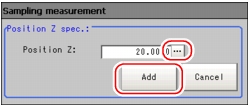
The Sampling Measurement window is displayed.
- Tap [...] for "Position Z" to set the spacer height ("20" or "10") and tap [Add].
 Note
Note- When entering height information, assume that the direction toward the camera is +.
The sampling result is displayed in "Sampling".
- Tap [3D coordinates parameter making] in the "3D coordinate parameter" area.
 Note
Note- This button is disabled if there is only one sampling data in [Sampling].
3D coordinate setting is performed and the result is displayed as a message.
When 3D coordinate setting is successful, a value is displayed in "Accuracy".
 Note
Note- Assuming the actual height at the reference surface is Z0, and the height calculated with 3D coordinate setting (calibration) parameter is Z, the accuracy is expressed with the formula below:
Accuracy = max{|Z(i)-Z0(i)|} (i: all the sampling points)
- Repeat the Steps
 2 to
2 to  12 when performing 3D measurement switching between Camera0+1 and Camera2+3.
 Note
Note- If information other than calibration target is in the field of view and sampling measurement is unsuccessful, adjust the sampling range with [Region setting].
Measurement when the Measured Object cannot be Placed Horizontally
Take samples at several points while moving the calibration target without specifying [Position Z].
- Tap [3D setting] in the "Item tab" area (top) and tap [3D coordinates] in the "Item tab" area (bottom).
- Select the combination of cameras to use in the "Set camera number" area.
- When using an all-in-one camera, uncheck "Availableness" of "The data camera has".
For an all-in-one camera, calibration is already set as factory default. Reset the calibration if the precision is insufficient.
 Note
Note- This item is displayed only when using an all-in-on camera.
- For an all-in-one camera, 3D coordinates setting parameters are provided as factory default.
When using an all-in-one camera, specify whether to use data inside the camera as 3D coordinates setting parameters.
Table:
3D Setting - 3D Coordinates (3D Camera Image)
|
Set Value [Factory Default]
|
|
|
When using an all-in-one camera, specify whether to use data inside the camera as 3D coordinate setting parameters.
|
|
|
|
The data inside the camera is used as 3D coordinate setting parameters.
|
|
The newly obtained data is used as 3D coordinate setting parameters.
|
- Set the "Optical condition setting" and "Sampling condition" as necessary. However, set the "Repetition frequency" for the "Sampling condition" area to "1".
- Select "Nothing" for "position Z spec." in the "Sampling" area.
- Place the calibration target as horizontal as possible on the point to be the reference surface (0mm point).
- Tap [Sampling measurement].
The Sampling Measurement window is displayed.
- Tap [Add].
The sampling result is displayed in "Sampling".
- With the calibration target tilted to the "right", "left", "forward", and "backward" at a height similar to the Step
 6, repeat the Steps
  7 and
7 and  8 for each direction.
Tilt so that the height is about the thickness of the spacer (2cm).
- Change the position of the calibration target (distance from camera) and repeat the Steps
 7 and
7 and  8 once more while it is "horizontal", and tilted "right", "left", "forward", and "backward".
- Tap [3D coordinates parameter making] in the "3D coordinate parameter" area.
 Note
Note- This button is disabled if there is only one sampling data in "Sampling".
3D coordinate setting is performed and the result is displayed as message.
When 3D coordinate setting is successful, a value is displayed in "Accuracy".
 Note
Note- Assuming the actual height at the reference surface is Z0, and the height calculated with 3D coordinate setting (calibration) parameter is Z, the accuracy is expressed with the formula below:
Accuracy = max{|Z(i)-Z0(i)|} (i: all the sampling points)
- Repeat the Steps
 2 to
2 to  11 when performing 3D measurement switching between Camera0+1 and Camera2+3.
 Note
Note- If information other than calibration target is in the field of view and sampling measurement is unsuccessful, adjust the sampling range with [Region setting].
 Note
Note 2 to
2 to  12 when performing 3D measurement switching between Camera0+1 and Camera2+3.
 Note
Note 4 of
4 of  Measurement when the Measured Object can be Placed Horizontally for the description of each item.
 6, repeat the Steps
  7 and
7 and  8 for each direction.
 7 and
7 and  8 once more while it is "horizontal", and tilted "right", "left", "forward", and "backward".
 2 to
2 to  11 when performing 3D measurement switching between Camera0+1 and Camera2+3.

