Timing Chart
When "Output Control" Is Set to "None"
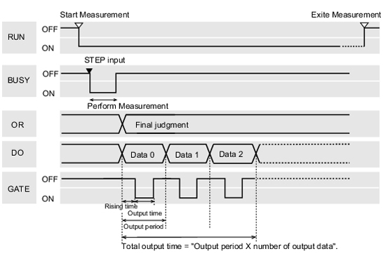
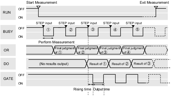
Output the measurement results if controller is not synchronous with external devices. Have the external devices detect the GATE signal of the controller, and load measurement results during ON status.
Inputting a measurement trigger in the STEP signal
Output signal
Outputs overall judgement. Selection of whether ON occurs during an OK judgement result or NG judgement result can be performed in the communication specifications settings window. | |
Outputs the results for expressions set in the processing item [Parallel Judgement Output]/[Parallel Data Output]. Selection of whether ON occurs during an OK judgement result or NG judgement result can be performed in the communication specifications settings window. | |
Input signal
Important
- When parallel continuous measurement is engaged and continuous STEP signal is input, switching of scene group should be avoided. When this is performed, set "Unchecked" in "Save scene group on switch scene" in either of the settings items below.
- Switch Scene Group window
 Switching Scene Groups
 - [Measure setting] in the [Measure] menu
 Setting Conditions Related to Operation during Measurement
- Switch Scene Group window
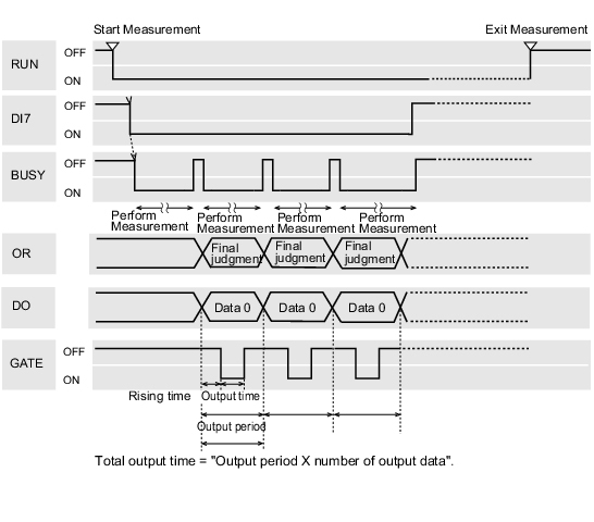
Continuous measurement
Important
- Measurement is given priority when continuous measurement is being performed. As a result, the measurement result display (overall judgement, image, judgement for each processing unit in the flow display, detailed results) may not be updated.
When continuous measurement ends, the measurement results of the final measurement are displayed.
- The output signal functions the same as when "Output Control" is set to "None".
 When "Output Control" Is Set to "None"
Input signal
When "Output Control" Is Set to "Handshaking"
Output the measurement results if controller is synchronous with external devices. If this function is used when multiple measurement results are output in sequence, it enables efficient and effective data transfer.
Inputting a measurement trigger in the STEP signal
- The output signal functions the same as when "Output Control" is set to "None".
 When "Output Control" Is Set to "None"
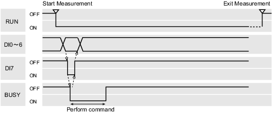
Input signal
When "Output Control" Is Set to "Synchronization Output"
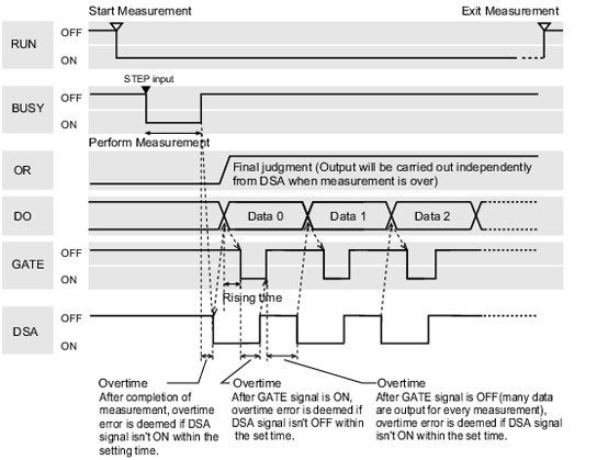
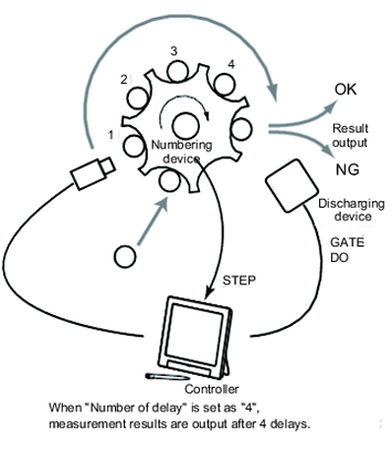
This method enables synchronization between processing timing on the line and timing for output of controller results. After the STEP signal has turned on the number of times set in "number of delay" in the communication specifications, measurement results will be output the next time the STEP signal turns on.
- When the communication specification "Output Control" is set to "Synchronization output", levels will be counted according to the number of times the STEP signal turns on. For this reason, perform settings so that results are output only once for each measurement. (1 unit for [Judgement Output], 1 data item for [Data Output])
 Setting Communication Specifications (Parallel Interface)
 - Only designate the STEP signal for measurement command input.
When measurement using serial commands and continuous measurement are performed, the output time will not match and this can cause controller malfunctions.
The discharge timing for when a defective part is found and the measurement results output timing can be synchronized.
Inputting a measurement trigger in the STEP signal
- The output signal functions the same as when "Output Control" is set to "None".
 When "Output Control" Is Set to "None"
Scene/Scene Group Switch
Output signal
Input signal Scene switching
Input signal Scene group switching
About Multiple Image Input Function
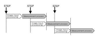
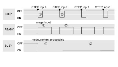
The function that enables continuous high speed image input is called the multiple image input function. The next STEP signal can be received at the point when image input is complete. It is not necessary to wait until measurement processing is complete. Whether image input is complete or not can be checked with the status of the READY signal.
In the case of FZ3-9
 /H9
/H9
 where two CPUs are installed, you can use the [Single-line High-speed mode] function that causes the two CPUs to alternately process measurement to shorten the shortest takt time*1 to as much as one half.
In the case of FZ3-9
*1: The shortest takt time refers to the shortest time over which a STEP can be accepted without generating a pool of captured images.
Important
- Set the image mode to "Freeze".
- When loading images continuously at high speed, the number of images that can be loaded is limited. Once the maximum number of images have been loaded, the READY signal will not turn on until the current measurement processing is complete. Accordingly, the next STEP cannot be input.
 About Max. Number of Loading Images during Multiple Image Input
 - If STEP is input while READY is off, the ERROR terminal turns on.
- Even if the image mode is "Through", the multiple image input function can be used. Note, however, that the READY signal is always off at this time and whether image input is complete cannot be observed from the outside. Even if the READY signal remains off, STEP signals can be accepted without the ERROR terminal turning on. Therefore, at this time, make the STEP signal input interval slightly longer than the image input time.
- If triggers are input continuously and too quickly for the communication output to catch up, some steps may not be output or measurement delays may occur. Input triggers at appropriate timings that do not cause communication delays.
- The multiple image input function cannot be used in the following cases:
- Multiple camera input processing units are present in the flow.
- An HDR+ camera is present in the flow.
- 1 camera input processing unit is used in multiple processes using the branching function.
- Measurement triggers are input other than in the parallel mode (such as when non-procedure commands or PLC-link measurement commands are sent).
