I/O Format (Parallel Interface)
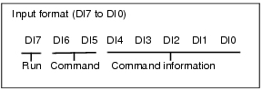
Input Format
- STEP signal
- DSA signalWhen "Output Control" is set to "Handshaking", this is a signal to provide notification that the external device is ready to receive data.
 Setting Communication Specifications (Parallel Interface)
 - DI signal
When 1 line is used
Clearing Measurement Values | Clear measurement values. The OR signal and DO signal are not cleared. | 1 | 10 | 00000 | Input example: 11000000 |
Clear Error | Clear error output. The ERROR indicator is also cleared. | 1 | 10 | 00001 | Input example: 11000001 |
Clear Parallel OR+DO | Clear the OR signal and DO signal. | 1 | 10 | 00010 | Input example: 11000010 |
Operation mode (FZ3-9
 /H9
/H9
 only) = [Multi-line random-trigger mode]

Item | Description | Input format (DI7 to DI0) | Input example | |||
|---|---|---|---|---|---|---|
Execute (DI7) | Command (DI6, DI5) | Line No. (DI4) | Command information (DI3 to 0) | |||
Continuous measurement | Measure continuously during input of commands. | 1 | 00 | 0 or 1 Specify the line number to send commands to. | ***** The controller does not see this signal, so a setting of either 0 or 1 makes no difference. | Continuously measure line 1 Input example: 10010000 |
Scene switch | Switch measurement scenes. | 1 | 01 | Input "Scene No." in binary format. | Switch line 0 to Scene 2 Input example: 10100010 | |
Scene group switch | Switch measurement scene groups. | 1 | 11 | Input "Scene Group No." in binary format. | Switch line 1 to Scene Group 2 Input example: 11110010 | |
Clearing Measurement Values | Clear measurement values. The OR signal and DO signal are not cleared. | 1 | 10 | 0000 | Clear the measurement values of line 1 Input example:11010000 | |
Clear Error | Clear error output. The ERROR indicator is also cleared. | 1 | 10 | 0001 | Clear the error of line 0 Input example: 11010001 | |
Clear Parallel OR+DO | Clear the OR signal and DO signal. | 1 | 10 | 0010 | Clear the OR signal and DO signal of line 1 Input example: 11010010 | |
0: OFF 1: ON
Important
- When parallel continuous measurement is engaged and continuous STEP signal is input, switching of scene group should be avoided. When this is performed, set "Unchecked" in "Save scene group on switch scene" in either of the settings items below.
- Switch Scene Group window
 Switching Scene Groups
 - [Measure setting] in the [Measure] menu
 Setting Conditions Related to Operation during Measurement
- Switch Scene Group window
Output Format
Output can be selected to turn on either when the judgement result is OK or when it is NG. The factory default setting is "ON at NG".
 Setting Communication Specifications (Parallel Interface)
The judgement results of judgement 0 to 15 set in the processing item [Parallel Judgement Output] are output to DO 0 to 15. | |
The measurement values set in data 0 to 7 in the processing item [Parallel Data Output] are output in 16-bit format.
Example) When [Parallel Judgement Output] is processing unit 5 and [Parallel Data Output] is processing unit 8  |
[Note 1]: If the operation mode (FZ3-9
 /H9
/H9
 only) is [Multi-line random-trigger mode], line 0 uses DO0 to DO7, while line 1 uses DO8 to DO15.
- After measurement, the data output by the OR signal or DO signal is held until the next measurement is performed. Note that the output status will be maintained even after measurement is complete.
However, when [One-shot OR signal] is on in Setting Communication Specifications (Parallel Interface), the OR signal will turn off after the set output time has elapsed.
 - The output signal factory default setting is OFF, but the signal may be ON for approximately 0.5 second when power is turned on. Be careful of signal loading occurring at external devices.
