Calibration (Camera Image Input)
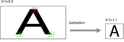
By setting the calibration, the measurement result can be converted and output as actual dimensions. The calibration method is selected here.
There are three calibration methods, point, sampling, and parameter.
 Note
Note- In order to output measurement results in actual dimensions, set [Calibration] to "ON" in [Output parameter] for each processing unit. If [Calibration] is "OFF" (factory default), measurement results are output as camera image coordinate values.
Specifying Points and Setting (Point Specification)
This is a method for performing calibration by specifying arbitrary points (in pixels).
Calibration parameters are calculated automatically when actual coordinates of specified locations are entered. Up to 3 points can be specified.
- When magnification is the same in the X and Y directions
- When magnification is not the same in the X and Y directions
 Note
Note- When 2 points are specified, the coordinate system is set to the left-hand system (forward in the clockwise direction). Specify 3 points to perform calibration including the coordinate system.
- In the item tab area, tap [Calibration].
- In the "Calibration setting" area, select "Point".
- Tap the first point on the screen.
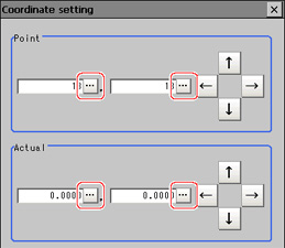
- Input the actual coordinates for the specified point.
The actual coordinate input window is displayed.
| Set value [Factory default] |
|---|
| 0 to 9999.9999 [Point you tapped in the window] |
| -99999.9999 to 99999.9999 [0] |
- Set the 2nd and 3rd points in the same way.
- Tap [Generate calibration parameters].
The calibration parameters will be generated.
Setting Calibration through Sampling Measurement (Sampling)
This is a method for setting calibration based on measurement results.
Calibration parameters are calculated automatically when a registered model is searched and the actual coordinates for that position entered.
- In the item tab area, tap [Calibration].
- In the "Calibration setting" area, select "Sampling" .
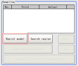
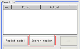
- In the "Sampling" area, tap [Regist model].
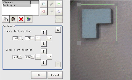
- Use the Drawing tools to register the model.
- Adjust the search region as necessary.
The default value setting is for the entire screen.
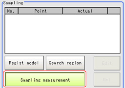
- Tap [Sampling measurement].
Measurement is performed.
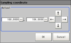
The search result (cross-shaped cursor) is displayed in the image display area, and the Sampling Coordinate window is displayed.
- In the sampling coordinate window, enter the X and Y values.
- Tap [OK].
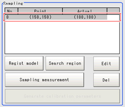
Point coordinates and actual coordinates are registered in the "Sampling" area.
- Move the object to be measured and repeat the Steps
 3 to
3 to  8.
8. - Tap [Generate calibration parameters].
The calibration parameters will be generated.
Inputting and Setting Values (Value Setting)
Enter calibration data directly with numerical values.
- In the item tab area, tap [Calibration].
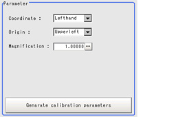
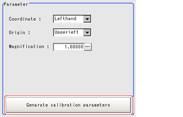
- In the "Calibration setting" area, select "Parameter".
- In the "Parameter" area, specify values for the "Coordinate", "Origin" and "Magnification".
| Set value [Factory default] | |
|---|
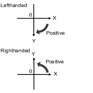
| | Left-hand type: Clockwise is forward when specifying the coordinates. Right-hand type: Counter-clockwise is forward when specifying the coordinates. |
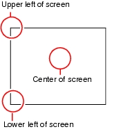
| [Upperleft], Lowerleft, Center | Select where the origin of the actual coordinates will be. |
| | Specify the ratio of 1 pixel to the actual dimensions. |
- Tap [Generate calibration parameters].
The calibration parameters will be generated.
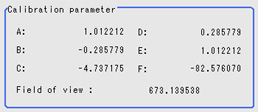
View Calibration Parameters
View the set calibration data.
- In the item tab area, tap [Calibration].
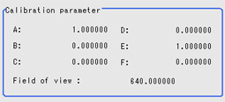
- In the ”Calibration parameter" area, confirm the calibration data.
| | |
|---|
| | These are calibration conversion values. Camera coordinates are converted to actual coordinates based on these values. The conversion formulas for actual coordinates are as follows: - (X, Y): Measurement point (camera coordinates), Unit: pix
- (X', Y'): Conversion point (actual coordinates)
|
| |
| |
| |
| |
| |
| | This is an actual dimension in the X direction. |
 3 to
3 to  8.
8.
