Points on Measurement Test and Adjustment (3D Circle Search)
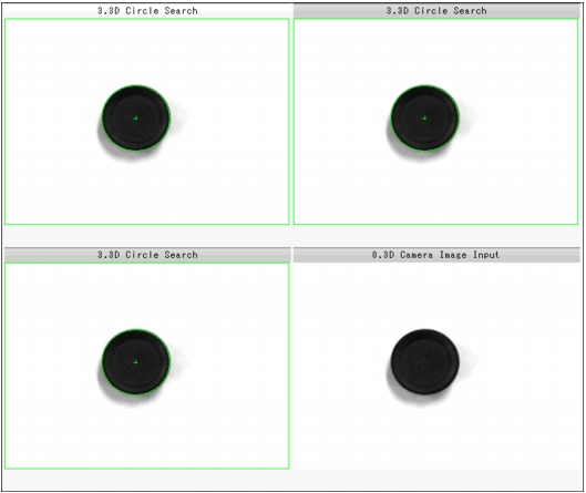
In addition to the image from the camera, the registered model region and the search coordinates (cross-shaped cursor) will also be displayed in the "Image display" area.
When two cameras are connected
Table:
Text Displayed (3D Circle Search)
|
|
|
|
|
X-coordinate of the position where the search circle is detected
|
|
Y-coordinate of the position where the search circle is detected
|
|
Z-coordinate of the position where the search circle is detected
|
|
Circle evaluated value in camera 0or 2 image
|
|
Circle evaluated value in camera 1or 3 image
|
|
Radius in camera 0or 2 image
|
|
Radius in camera 1or 3 image
|
|
Allowable deviation for camera 1 relative to camera 0. This item specifies the allowable value for the relative camera shift that may occur after 3D coordinates are set.
|
When three cameras are connected
Table:
Text Displayed (3D Circle Search)
|
|
|
|
|
X coordinate of the position where the search circle is detected
|
|
Y coordinate of the position where the search circle is detected
|
|
Z coordinate of the position where the search circle is detected
|
|
Camera 0 image circle evaluated value
|
|
Camera 1 image circle evaluated value
|
|
Camera 2 image circle evaluated value
|
|
Radius on the camera 0 image
|
|
Radius on the camera 1 image
|
|
|
|
Allowable deviation for camera 1 relative to camera 0
|
|
Allowable deviation for camera 2 relative to camera 0
|
|
Specify this item only when three cameras are connected. This item represents the allowable difference when the same coordinates are measured with two systems: camera 0+1 and camera 0+2.
|
 User's Manual, "Displaying Flow and Detail Result"