[Region setting (Defect)]
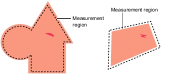
The measurement region for [Defect] is specified with rectangle, circle (ellipse), circumference, arc, or polygon.
When drawing the measurement region, measurement is performed on the displayed image, with the measurement results being registered as the reference (used as the X and Y Coordinate to find the position of defects). For this, when drawing the measurement region, the measurement object should be correctly placed.
 Note
Note- Do not draw the measurement region in places with marks and patterns because this will not discriminate defects and stains.
- When the measurement region is lower than the Lower limit of defect size, the measurement results may become NG.
For the defect detection size, Please Ellipse to [Measurement (Defect)].
Table:
Region Setting Method (Defect)
|
|
|
Selected when detecting defects and stains of the measurement objects. Up to 8 figures can be drawn. When multiple figures are drawn, Region inspection mode is used.
|
|
Selected when detecting defects and stains of the circle objects. Up to 8 figures can be drawn. When multiple figures are drawn, Region inspection mode is used.
|
|
Selected when detecting the overall defects of specified zones and measurement objects. Up to 8 shapes (straight line, rectangle, oval, circle, circumference, arc, polygon) can be combined when drawing a figure (Region inspection mode).
|
- In the "Item tab" area, tap [Region setting].
- When a measurement region is already registered, tap [Edit]. When no measurement region is registered, go to Step 3.
The "Figure setting" area is displayed.
- Specify the measurement region using Drawing Tools.
- In the "Figure setting" area, tap [OK].
The measurement region is registered and displayed in the "Image display" area.
 [Measurement (Defect)].
 Setting up [Defect].


