[Screen Adjust (Camera Image Input)]

The following items can be set up in the Screen adjustment option.

Lighting Control

The brightness of the lighting can be adjusted from the controller. You can choose to adjust the brightness for each part or select one of the preset patterns.
Note
  • Perform the lighting setting only when the camera being used has lighting equipment.
  • When one scene contains two or more Camera Image Input units, lighting control can be performed only for the first Camera Image Input unit.
  1. In the "Item tab" area, tap [Screen adjust].
    Screen adjustment
  2. In the "Lighting control" area, specify the brightness.
    The displayed content depends on the connected camera.
    When an intelligent camera is connected
    Set the brightness of parts 0 to 7 between the range of 0 and 255.
    Brightness 0 indicates the lighting is OFF. The larger the number, the higher the brightness.
    Important
    • When model FZ-SLC15 is connected, only parts 0 to 3 are active. Changing parts 4 to 7 will not affect the brightness.
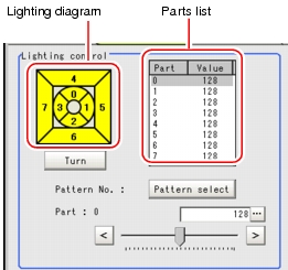
    1. Check the part in the lighting diagram and tap the number of the part to set in the parts list.
      Screen adjust - Lighting control area
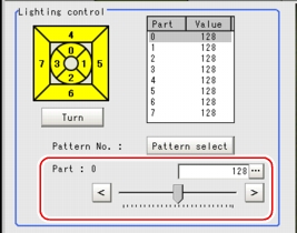
    2. While verifying the camera-input image in the "Image display" area, drag the slider to adjust the brightness.
      To fine-tune, tap the buttons at both ends of the slider.
      The "Value" for the selected part changes.
      Screen adjust - Lighting control area
      A lighting image is displayed as a diagram.
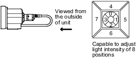
      Illustration of the lighting position of camera
      Table: Screen Adjust (Camera Image Input) - Lighting Setting
      Item
      Set Value
      [Factory Default]
      Description
      Brightness
      [0] to 255 x 8ch
      Adjustable in 256 steps
    Note
    When selecting a preset lighting pattern:
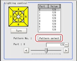
    • Tap [Pattern select] and select one of the preset lighting patterns. The selected pattern contains brightness settings to be applied to the respective parts.
      Screen adjust - Lighting control area
      The following table shows the brightness settings in each pattern.
      Table: Block Adjustment Pattern
      Block Adjustment Pattern
      Part 0
      Part 1
      Part 2
      Part 3
      Part 4
      Part 5
      Part 6
      Part 7
      Pattern 0
      128
      128
      128
      128
      128
      128
      128
      128
      Pattern 1
      255
      255
      255
      255
      255
      255
      255
      255
      Pattern 2
      128
      128
      128
      128
      0
      0
      0
      0
      Pattern 3
      255
      255
      255
      255
      0
      0
      0
      0
      Pattern 4
      0
      0
      0
      0
      128
      128
      128
      128
      Pattern 5
      0
      0
      0
      0
      255
      255
      255
      255
      Pattern 6
      255
      0
      255
      0
      255
      0
      255
      0
      Pattern 7
      0
      255
      0
      255
      0
      255
      0
      255
      Pattern 8
      255
      0
      0
      0
      0
      0
      0
      0
      Pattern 9
      0
      255
      0
      0
      0
      0
      0
      0
      Pattern 10
      0
      0
      255
      0
      0
      0
      0
      0
      Pattern 11
      0
      0
      0
      255
      0
      0
      0
      0
      Pattern 12
      0
      0
      0
      0
      255
      0
      0
      0
      Pattern 13
      0
      0
      0
      0
      0
      255
      0
      0
      Pattern 14
      0
      0
      0
      0
      0
      0
      255
      0
      Pattern 15
      0
      0
      0
      0
      0
      0
      0
      255
      Pattern 16
      0
      0
      0
      0
      0
      0
      0
      0
    Change lighting number
    • After the camera is installed, if the orientation of the camera does not match the orientation of the lighting parts, tap [Turn] under the lighting diagram. The lighting diagram rotates 90 degrees clockwise each time you tap [Turn], so that you can make the lighting part positions correspond to the actual lighting part positions.
      Illustration about the obtain of the lighting
    For MG-WAVE connection:
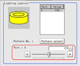
    Set the brightness between the range of 0 and 255.
    Brightness 0 indicates the lighting is OFF. The larger the number, the higher the brightness.
    1. While verifying the camera-input image in the "Image display" area, drag the slider to adjust the brightness.
      To fine-tune, tap the buttons at both ends of the slider.
      The "Value" for the brightness changes.
      Screen adjust - Lighting control area
      A lighting image is displayed as a diagram.
    Note
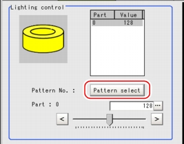
    When selecting a preset lighting pattern:
    • Each time you tap [Pattern select], the lighting pattern is switched to the next preset pattern.
      Screen adjust - Lighting control area
      The following table shows the brightness settings in each pattern.
      Table: Adjustment Pattern
      Adjustment Pattern
      Part 0
      Pattern 0
      128
      Pattern 1
      255
      Pattern 2
      0
    For other cameras
    The brightness cannot be adjusted. The following message appears in the "Lighting control" area.
    Screen adjust - Lighting control area

Lens Setting (When Connecting an Intelligent Camera or an Auto-focus Camera)

Adjust the lens of the camera.
The optimum value can be set automatically for focus and iris (auto focus, auto iris).
Depending on the focus setting, it may not be possible to set a large zoom value.
  1. In the "Item tab" area, tap [Screen adjust].
    Screen adjust
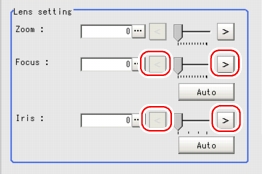
  2. While verifying the image in the "Image display" area, drag the slider in the "Lens setting" area.
    Screen Adjust - Lens Setting Area
    Table: Screen Adjust (Camera Image Input) - Lens Setting
    Item
    Set Value
    [Factory defaults]
    Description
    Zoom
    0 to [1023]
    Switches between wide and telephoto by enlarging the image and performing interpolation.
    When fine-tuning
    Tap the buttons at both ends of the slider.
    Screen Adjust - Lens Setting Area
    Specifying a value directly:
    Tap [...] for "Zoom" and input a value.
    For how to input value, see User's Manual, "Inputting a Value"
    Screen Adjust - Lens Setting Area
  3. In the "Lens setting" area, specify values for "Focus" and "Iris".
    Table: Screen Adjust (Camera Image Input) - Lens Setting
    Item
    Set Value
    [Factory defaults]
    Description
    Focus
    [0] to 1023
    Adjust the focus.
    Iris
    [0] to 31
    Adjust the amount of light that passes through the lens.
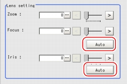
    Setting optimum values calculated automatically:
    Tap [Auto] at the right of each item.
    An appropriate value is calculated and set.
    Screen Adjust - Lens Setting Area
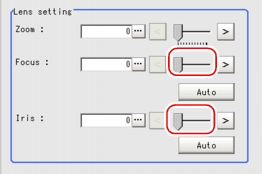
    When adjusting the values manually
    Drag the slider while verifying the image in the "Image display" area.
    After the automatic setting, individual fine-tuning can still be performed.
    Screen Adjust - Lens Setting Area
    Fine-tuning
    Tap the buttons at both ends of the slider.
    Screen Adjust - Lens Setting Area

Common Setting for All Cameras (When Connecting an Intelligent Camera or an Auto-focus Camera)

  1. In the "Item tab" area, tap [Screen adjust].
    Screen adjust
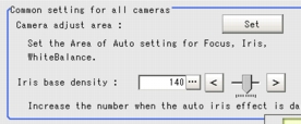
  2. In the "Common setting for all cameras" area, set up "Camera adjust area" and "Iris base density".
    Screen Adjust - Common Setting for All Cameras Area
    Setting up "Camera adjust area"
    Specify the target area to apply automatic settings for focus, iris, and white balance.
    1. Tap [Set] for "Camera adjust area".
      The "Figure setting" area is displayed.
    2. Specify the target area using the Drawing Tools.
      Screen Adjust - Detail Area
    When setting up "Iris base density"
    Specify a larger value when the result with the automatic iris setting is dark.
    1. Tap [...] for "Iris base density" and specify a value.
      For how to input value, see User's Manual, "Inputting a Value"
      The value can be adjusted by dragging the slider or by tapping the buttons at both ends of the slider.