Image Display Setting
Displaying Multiple Images in the Window
Multiple images can be displayed side by side in the "Image display" area.
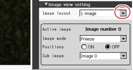
- In [Image view setting] in the "Control" area of the Main screen, tap [
 ] for "Image layout" and select the number of images to display.
The displayed images in the "Image display" area change according to the selection.
 Note
Note- An alternative operation: tap [View] - [Image layout].
There are following four patterns of image display.
Table:
Image display pattern
|
|
|
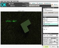
1 image. Since images are Zooming, it is ideal for you to see the Details. The image of the processing unit selected in the measurement flow is displayed.
|
|
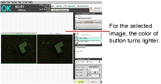
2 images are viewed side by side.
Suitable for connecting two cameras whereby images can be checked side by side.
|
|
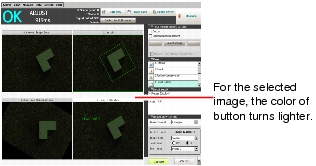
4 images are viewed together with each one at the left, right, upper, and lower position.
Suitable for connecting 4 cameras whereby images are checked at one time.
|
|
Shows four small images on the bottom, and one bigger image above of the one selected from the four.
This view is preferable when you wish to check details of a certain image when connecting four cameras.
Thumbnail is not available with "RUN - fast view mode". When displaying with Thumbnail in the ADJUST window, if you switch to RUN - fast view mode, the display will change to 4 images.
|
Important
- When displaying multiple images, the processing unit of measurement flow can be displayed with each image. By selecting an image by pointing and then tapping the processing unit of measurement flow, the Unit No. of the processing unit is set.
When switching from one image display to multiple image display, if Unit No. for each image is not set, Unit No. 0 (default) is selected.
 Note
Note
The available options for the case whereby more than one image is viewed
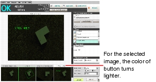
- The color of ProcItem setting button turns to white.
- While displaying flow information or detailed information, if image selection is changed in the "Image display" area, the following contents will change according to the selected image.
- Selected processing unit in the measurement flow (the processing unit with blue background color)
- Displayed content of detailed information
- While selecting images in the "Image display" area, if the selection of processing unit is changed in the measurement flow, the image selected in the "Image display" area switches according to the reselected processing unit in the measurement flow. However, other images in the "Image display" area do not change.
- After switching the selection from camera images to saved images, if you delete a saved image, the display of the location where the image was shown becomes black.
Listing Measurement Results
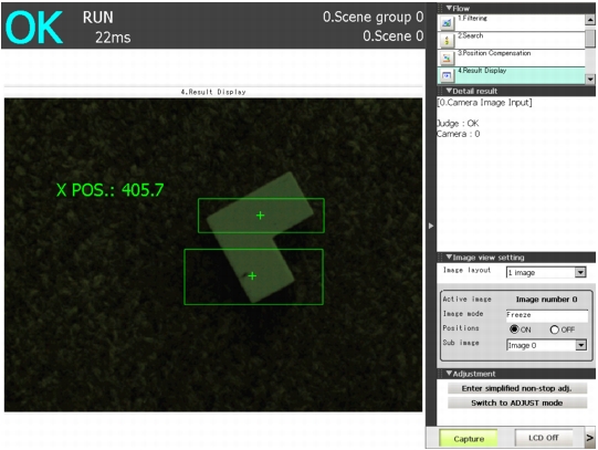
By using "Positions", you can display the positions of measurements of multiple processing units in the "Measured image" area. Listing positions makes it easier to know the situation of entire inspection.
 Note
Note- An alternative operation: tap [View] - [Positions].
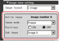
- Set each item in [Image view setting] of the "Control" area.
Table:
Image display
|
|
|
The number of currently selected image (0 to 3) is displayed. When the "Detail result" area is active, the string "Detail result" is displayed.
|
|
|
|
Sets ON/OFF of Positions. While Positions is ON, the processing unit you can select is one of Camera Image Input, Camera Switching, and Position Compensation. If you switch OFF to ON, Camera Image Input, Camera Switching, and Position Compensation above the currently selected Unit No. will be selected automatically.
|
|
By changing the "Sub image", you can switch the content of the measurement results to be displayed. Number of displayed Sub images differs depending on processing item. For the Sub image number of each processing item, see  List of Sub image number List of Sub image number. For processing items not listed in the list of the Sub image number, the same measurement result is displayed regardless of the setting of the Sub image number.
|
Table:
List of Sub image number
|
|
Sub image number and display
|
|
|
|
|
0: Measured image 1: Profile display
|
|
0: Measured image 1: Extracted image
|
|
0: Measured image 1: Profile display
|
|
0: Measured image 1: Extracted image
|
|
0: Measured image 1: Difference image
|
|
0: Measured image 1: Measured image together with matched edges
|
|
0: Measured image 1: Defect profile [with area measurement]
|
|
0: Measured image 1: Scanning region
|
|
0: Measured image 1: Scanning region
|
|
3D Camera Image Input 3D Height 3D Search 3D Circle Search
|
Depending on the 3D setting and camera setting, displayed images change. 0: Measured image from camera 0 or camera 2 1: Measured image from camera 1 or camera 3 2: Measured image from camera 2 [Note 1] |
|
0: Measured image from camera 0 or camera 2 1: Measured image from camera 1 or camera 3
|
|
0: Measured image from camera 0 or camera 2 1: Display of image profile from camera 0 or camera 2 2: Measured image from camera 1 or camera 3 [Note 2]3: Display of image profile from camera 1 or camera 3 [Note 2]
4: Measured image from camera 2 [Note2]
5: Display of image profile from camera 2 [Note 2] |
[Note 1]: When measuring with camera 0+1+2
[Note 2]: When the measured coordinates, measurement region, and profile display of sub image 2 to 5 is measured by 3D edge measurement with camera 0+1+2, camera 0+1 and camera 0+2 are switched automatically inside. Therefore, the number displayed changes depending on whether the measurement is performed with camera 0+1 or camera 0+2.
The outline of switching camera 0+1 and camera 0+2 is as follows:
With camera 0+1, the edge along the horizontal direction is measured. The edge along the vertical direction cannot be measured.
With camera 0+2, the edge along the vertical direction is measured. The edge along the horizontal direction cannot be extracted.
The displayed images in the "Image display" area change according to the selection.
Changing the Camera Image Mode (ADJUST Window Only)
Select the type of camera images shown in "Image display" area.
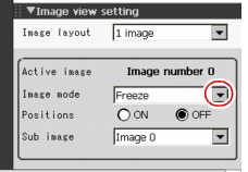
- In [Image view setting] in the "Control" area, tap [
 ] for "Image mode" and select a mode for camera images.
 Note
Note- An alternative operation: tap [View] - [Image mode].
Table:
Type of Camera Images
|
|
|
The latest images are always captured from cameras and displayed in image view area.
The following operations are not available with Through.
- Re-measurement
- Display Saved images
|
|
Display the images acquired during the last measurements. These imaged can be updated at all times.
|
|
Display Last NG images according to the overall judgement result. The latest measurement results are always shown in overall judgement and measurement time. In such case, the overall judgement result and measurement time may conflict with camera images.
|
Switch camera image view in the "Image display" area according to the selected contents.
 Note
Note- When displaying the Last NG and making it active, if you tap the "Image display" area or a flow, the screen is cleared. To capture the Last NG, do it before performing another operation.
- With the status of multiple inputs or when a measurement trigger is entered immediately after BUSY is turned OFF, the Last NG cannot be displayed.
 List of Sub image number.
 ] for "Image mode" and select a mode for camera images.
 Note
Note