Setup of Camera & Software Vision Package
Prepare hardware
At first prepare hardware components to construct the system.1. essential : PC
2. essential : GigE Cameras ( in the quantity required )
3. essential : Gigabit Ethernet adapter (PoE type is recommended)
4. as appropriate : External power supply unit for cameras ( In case PoE is not used )
5. as appropriate : PoE Injector
6. as appropriate : Switching HUB ( In case multiple cameras are used )
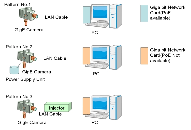
Shown below are the combinations of quantity of cameras, and type of power supply.| index |
Quantity of Cameras |
Power supply |
|---|---|---|
| 1 |
1 unit |
PoE Gigabit Ethernet adpter |
| 2 |
1 unit |
External power source |
| 3 |
1 unit |
PoE Injector |
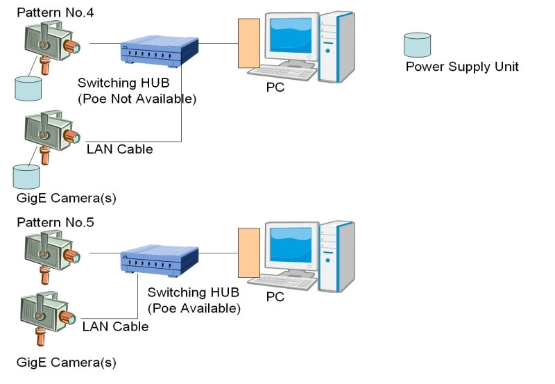
| 4 |
Multiple units |
External Pwer supply unit (for each cameras) |
| 5 |
Multiple units |
PoE Switching HUB |
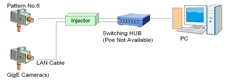
| 6 |
Multiple units |
PoE Injector |
IMPORTANT
The LAN for communication with cameras is for communication with cameras only.Don't use for communication with other devices.
When PoE camera is connected to PoE power sourcing equipments, such as PoE switching hub or PoE injector, camera can be powered via network cable.
For FJ Series, VGA type and 2M type cameras are PoE cameras.
Install Gigabit ethernet adapter
Following manufacturer's instructions, install Gigabit ethernet adapter hardware and device driver software.
Install GigE camera device driver
Following the steps shown below, device drivers of camera and dongle from installation CD.
Here are the installation procedure for Windows XP PC using installation CD.
( There can be slight difference in procedure or screen display, depending on OS and type of installation CD.)
1. Insert installation CD into PC. Then setup program starts automatically.
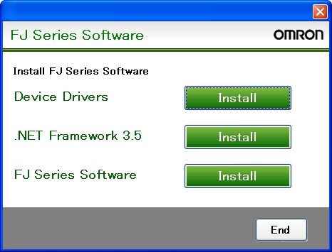
2. Press "Install" button for device driver. Then setup for camera device driver starts. Please install it with default option, if there is no special reason to change.

3. After installation of camera device driver, then setup for dongle device driver starts. Please install it with default option, if there is no special reason to change.
4. After installation of dongle device driver, return to setup program ( step 1. ).
- Installation of device driver must be done by Administrator authority.
- Before installation, FJ software must be terminated.
- Displayed messages can have slight difference, depends on the version, or operating system on PC.
Configure Gigabit Ethernet adapter
After device driver installation, you must configure Gigabit Ethernet adpter.The description in this section assume connecting one camera per one ethernet adapter.
In case you need to connect nultiple cameras, please refer to "Connecting multiple cameras" describled later.
Network configuration (Protocol)
Configure network following the steps below.for Windows XP
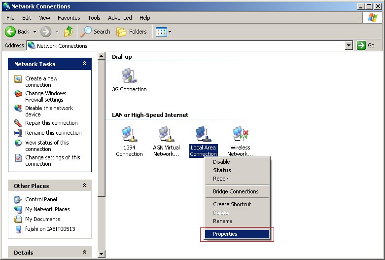
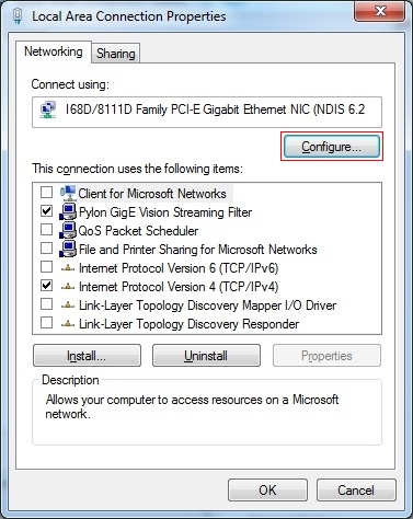
1. Open "Property" from Control panel -> Network Connections -> LocalArea connection.
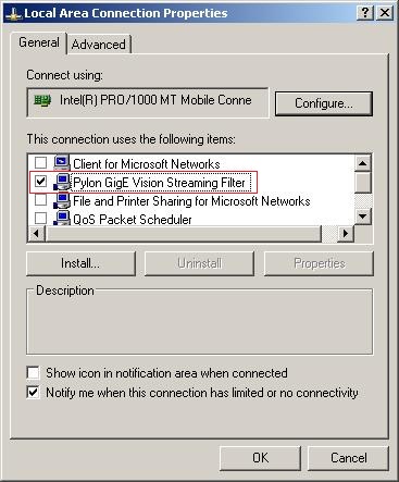
2. Uncheck all the items except "Pylon GigE Vision Streaming Filter" and "Internet Protocol(TCP/IP)".
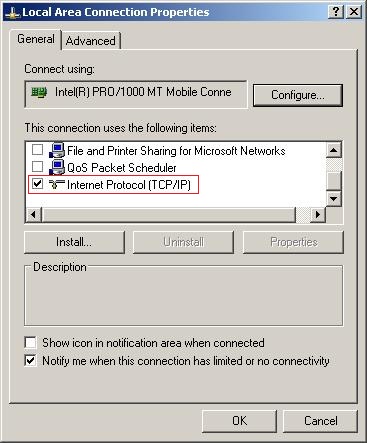
3. Select "Internet Protocol(TCP/IP)", and press "Property".
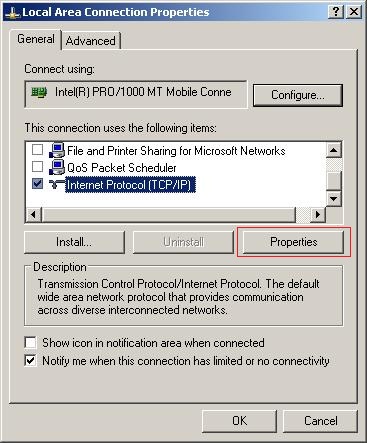
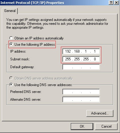
4. Select "Use the following IP address", set the following addresses.
After that, press OK button and close all the dialog.
| Item |
value |
|---|---|
| IP address |
192.168.1.1 |
| Subnet mask |
255.255.255.0 |
for Windows 7
1. Open "Property" from Network Connections -> Local Area Connection.
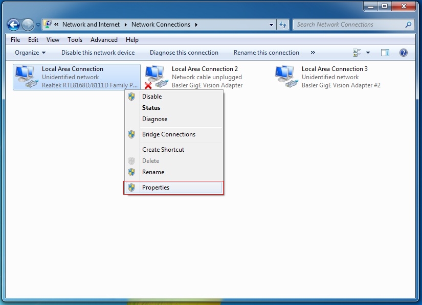
2. Uncheck all the items except "Pylon GigE Vision Streaming Filter" and "Internet Protocol(TCP/IP)".
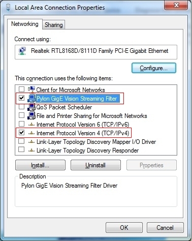
3. Select "Internet Protocol Version 4(TCP/IPv4)", and press "Property".
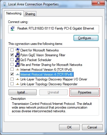
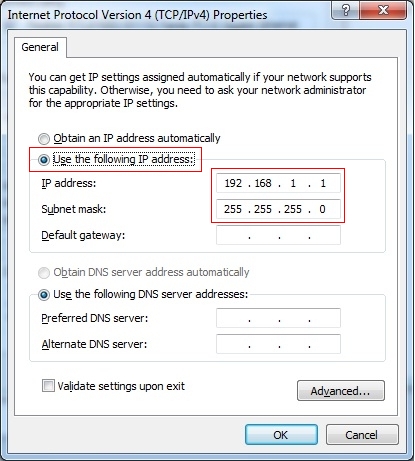
4. Select "Use the following IP address", set the following addresses.
After that, press OK button and close all the dialog.
| Item |
value |
|---|---|
| IP address |
192.168.1.1 |
| Subnet mask |
255.255.255.0 |
Network configuration (Detail)
Configure detailed network parameters following the steps below.for Windows XP
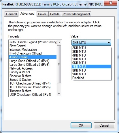
1. Open "Configure" from Control panel -> Network Connections -> LocalArea connection.
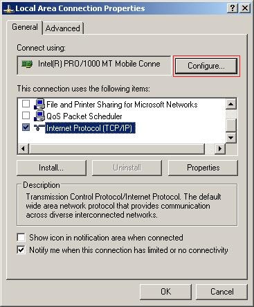
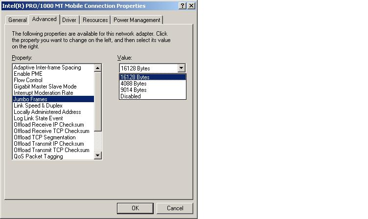
2. Select "Advanced" tab, and set the following parameters.
Your network adapter may show the parameters in different name, or some of the parameters are not supported.
| item |
value |
description |
|---|---|---|
| Jumbo Frame |
Maximum value supported by network adapter |
Size of data for one cycle of communication. Setting bigger value makes the data transimission more efficient. |
| Receive Descriptor |
Maximum value supported by network adapter |
The parameter related to the capacity of a receive buffer. |
| Interrupt Moderation rate |
Minimum value |
The quantity of interrupt to CPU for each received packet. |
| Speed and Duplex Mode |
Automatic |
Speed and communication mode. |
For Windows 7
1. Open "Configure" from Network Connections -> Local Area Connection.
2. Select "Advanced" tab, and set the following parameters.
Your network adapter may show the parameters in different name, or some of the parameters are not supported.
| item |
value |
description |
|---|---|---|
| Jumbo Frame |
Maximum value supported by network adapter |
Size of data for one cycle of communication. Setting bigger value makes the data transimission more efficient. |
| Receive Descriptor |
Maximum value supported by network adapter |
The parameter related to the capacity of a receive buffer. |
| Interrupt Moderation rate |
Minimum value |
The quantity of interrupt to CPU for each received packet. |
| Speed and Duplex Mode |
Automatic |
Speed and communication mode. |
Firewall settings
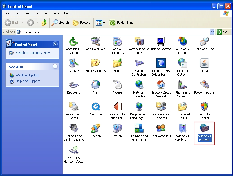
Change configuration of firewall following the steps below.For Windows XP
1. Double-click "Windows firewall" from Control panel.
2. Select "General" tab, and check "On".
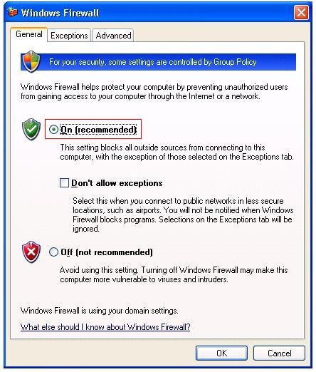
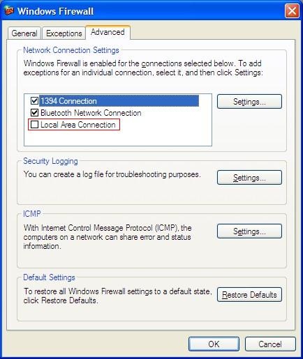
3. Select "Advanced" tab and uncheck the network adapter to connect camera.
Press OK and close the dialog.
For Windows 7
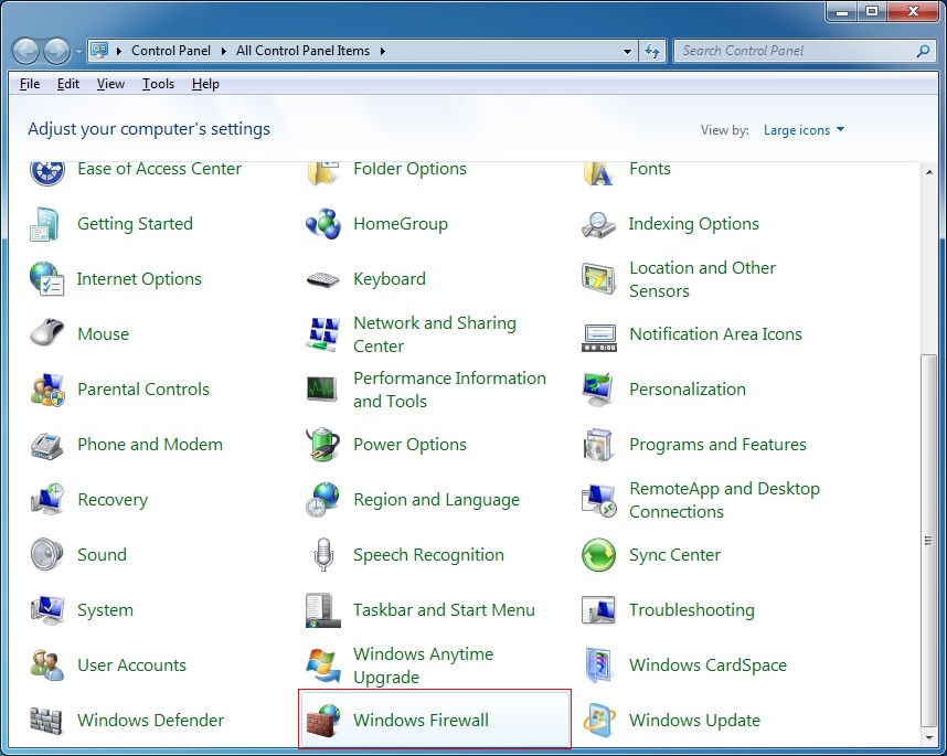
1. Double-click "Windows firewall" from Control panel.
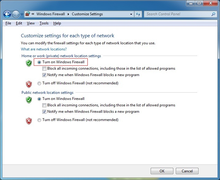
2. Check "Turn on Windows Firewall" for "Home or work (private) network location settings.
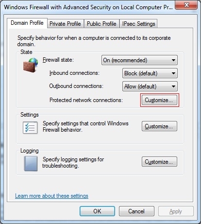
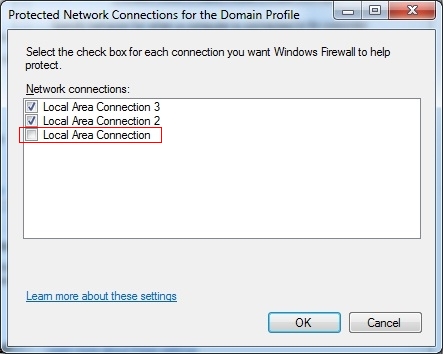
3. Open "Windows firewall property" and select "Protected network connections".
Uncheck the network adapter to connect camera. Press OK and close the dialog.
Connection of cameras
Connect FJ cameras to FJ system following the steps below.1. Connect FJ-VSP to DC 12V power source.
Brown : +12V blue : GND
2. Conenct FJ-VSG and FJ-VSP to FJ camera, and turn on the power.
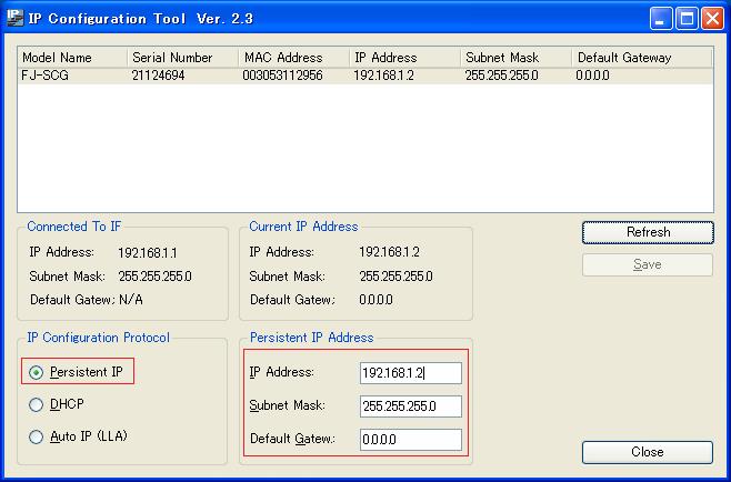
3. Launch "IP Configuration Tool" by double-clicking the shortcut.

4. Make sure the FJ camera is listed on "Model Name".
In case no camera is listed, press "Refresh" button, and check that camera appears on the list.
( In some cases, it takes approximately 30 seconds for detecting camera connection. If no camera is listed, press "Refresh" button after waiting for a while. )
5. Check "Persistent IP" on "IP Configuration Protocol", and set the value below to "Persistent IP Address".
Press "Save" button and close the program.
| item |
value |
|---|---|
| IP Address |
192.168.1.2 |
| Subnet Mask |
255.255.255.0 |
| Default Gateway |
0.0.0.0 |
Connecting multiple cameras
There are two ways for connecting multiple cameras.1. Add network adapter.
- Install multiple network adapters.
- Use network adapter with multiple ports.
2. Use switching HUB.
IMPORTANT
FJ software does not support hot-plug for camera network cable. Hot-plug may cause unstadiness of system behavior.Setup of FJ Software
Installation
Setup standard FJ software from FJ-SW installation CD, following the steps below.
1. Insert installation CD into PC. Then setup program starts automatically.
2. Press "Install" button for FJ Series Software. Then setup for camera device driver starts.
To install the software developped by Application Producer FJ-AP1, refer to  Development support tool on Application Producer.
Assign a camera number
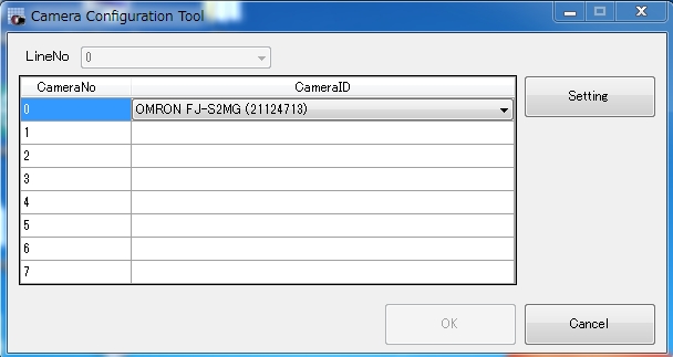
Following the steps below, assign a camera number for each cameras connected.1. Launch "Camera Configuration Tool".
2. Select camera from the list to each camera number (CameraNo).
Detailed setting for cameras
1. Press "Setting" button on Camera Configuration Tool, then detailed settng dialog for selected camera will appear.
These are the parameters.
| Category |
item |
value |
decsription |
|---|---|---|---|
| External trigger |
Line invert |
Enable Disable |
Invert trigger polarity. Enable:Invert(Photocoupler OFF) Disable:Not invert(PhotocouplerON) |
| Trigger delay time(μs) |
0 - 1000000 |
Set the time from recognizing trigger to releasing the shutter of a camera. |
|
| Trigger sensing pulse-width time(μs) |
0 - 20000 |
Set the pulse-width time for recognizing trigger of a camera. |
|
| Output port setting |
Signal select |
Trigger ready Strobe trigger |
Trigger ready:The signal which is ON while trigger signal can be input Strobe trigger:The signal for strobe trigger. |
| Line invert |
Enable Disable |
Invert signal select polarity. Enable:Invert(Photocoupler OFF) Disable:Not invert(PhotocouplerON) |
|
| Strobe trigger setting |
This setting is valid when Signal select is "Strobe trigger". |
||
| Signal delay time(μs) |
0 - 4095 |
Set the delay time of "Strobe trigger". |
|
| Signal pulse-width time(μs) |
0 - 4095 |
Set the pulse-width time of "Strobe trigger". |
|
| I/O monitor |
TRG port |
ON OFF |
Indicate the input state of TRG port. |
| Output port |
ON OFF |
Indicate the output state of Output port. |
|
| Ethernet |
Packet size |
220 - 16404 |
Set the packet size for transmitting from a camera. |
| Inter-Packet delay |
FJ-SCG:0 - 42864 FJ-SG:0 - 86251 FJ-SC2MG:0 - 16430 FJ-S2MG:0 - 35579 FJ-SC5MG:0 - 439 FJ-S5MG:0 - 3736 |
Set the delay time of packets between. Set for preventing packet-loss becase of connecting multiple cameras in one LAN. Set with Packet transmission delay. |
|
| Packet transmission delay |
0 - 50000000 |
Set the delay time to transmit packets. Set for preventing packet-loss becase of connecting multiple cameras in one LAN. Set with Inter-Packet delay. |
|
2. Press OK button and the changes are enabled.
Pressing "Restore the default setting" restores default setting.
Configuration of Processing Item "Camera Image Input GigE"
Refer to Reference : Camera Image Input GigE.
Making measurement flow
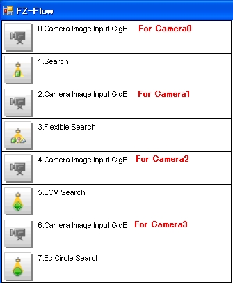
You must allocate "Camera Image Input GigE" unit for each GigE cameras connected to the system.In each unit, you need to select camera to handle.
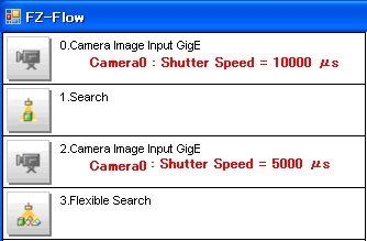
One camera can be handled by multiple "Camera Image Inut GigE" units. In this case, each unit receives camera image with modified camera parameters following the measurement flow.
example 1: Add four "Gamera Image Input GigE" units to use four cameras.
Others
Make these configuration depending on system constitution.IMPORTANT
FJ software, Camera configuration tool, and IP Configuration Tool can't execute properly when start in parallel.When use these software, check other softwares are not executed.