Setting Communication Specifications (RS-232C/422-PLC Link)
Communication specifications such as link areas or communication speed and data length are set.
 Setting Communication Specifications (Ethernet - PLC Link)
Important
- Use the same communication specification settings for the controller and the external device.
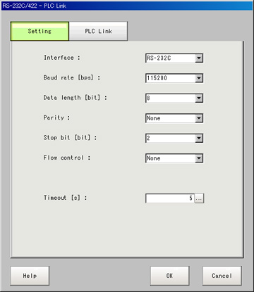
- On the Main screen, tap the [System] menu - [Communication] - [Serial] - [RS-232C/RS-422].The serial interface window is displayed.
- In the communication setting area, set the following items.
 Setting itemSet value
[Factory default]DescriptionInterface- [RS-232C]
- RS-422
Adjust to the PC communication specifications.Baud rate [bps] [Note 1]- 2400
- 4800
- 9600
- 19200
- [38400]
- 57600
- 115200
Adjust to the PC communication specifications.Data length [bit]- 7
- [8]
Adjust to the PC communication specifications.Parity- [OFF]
- Odd
- Even
Stop bit [bit]- 1
- [2]
Flow control[OFF]Flow control is not performed with software.
If the time in which there is no response from external devices reaches the timeout setting time, a timeout error occurs and an error message is displayed in the window.The parallel interface ERROR signal also turns on.Xon/XoffFlow control is performed with software.Data is sent according to the Xon/Xoff codes from external devices.Timeout [s]1 to 120
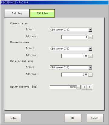
[5]Set the time in which a timeout error will occur in seconds.[Note 1]: If a speed of [38400 bps] or higher is selected, effective communication cannot be guaranteed depending on the cable length because speeds of over 20 kbps are not defined in RS-232C standards.In these cases, set the communication speed at [19200 bps] or lower. - Tap [PLC Link setting].The PLC Link Setting window is displayed.
- Set the following items.
 Setting itemSet value
[Factory default]DescriptionCommand areaArea- [CIO Area(CIO)]
- Work Area(WR)
- Holding Bit Area(HR)
- Auxiliary Bit Area(AR)
- DM Area (DM)
- EM Area(EMO)
Set the "Communication" area.Address0 to 99999
[0]Set the communication address.Response areaArea- [CIO Area(CIO)]
- Work Area(WR)
- Holding Bit Area(HR)
- Auxiliary Bit Area(AR)
- DM Area (DM)
- EM Area(EMO)
Set the "Communication" area.Address0 to 99999
[100]Set the communication address.Data output areaArea- [CIO Area(CIO)]
- Work Area(WR)
- Holding Bit Area(HR)
- Auxiliary Bit Area(AR)
- DM Area (DM)
- EM Area(EMO)
Set the "Communication" area.Address0 to 99999
[200]Set the communication address.Retry interval [ms]1000 to 999999
[10000]Set the communication retry interval. - Tap [OK].The settings are confirmed and the serial interface window closes.
Checking Communication Status
Use PLC tools, etc. to check the communication status.