Setting Communication Specifications (Ethernet - PLC Link)
Communication specifications such as link areas or communication speed and data length are set.
 Setting Communication Specifications (RS-232C/422-PLC Link)
Important
- Use the same communication specification settings for the controller and the external device.
- When making system settings/Ethernet settings, do not send external input into the Ethernet.
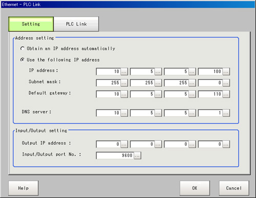
- On the Main screen, tap the [System] menu - [Communication] - [Serial] - [Ethernet].The Ethernet window is displayed.
- In the communication setting area, set the following items.
 Setting itemSet value
[Factory default]DescriptionAddress setting- Obtain an IP address automatically
- [Use the following IP address]
Set the IP address of the controller.
When "Obtain an IP address automatically" is selected, the IP address of the controller will be automatically obtained.
When "Use the following IP address" is selected, set the IP address, subnet mask, and the default gateway address.a.b.c.d
a: 1 to 223
b: 0 to 255
c: 0 to 255
d: 0 to 255
[10.5.5.100]Input the controller IP address.0.0.0.0 to 255.255.255.255
[255.255.255.0]Input the subnet mask address.0.0.0.1 to 255.255.255.254
[10.5.5.110]Input the default gateway address.a.b.c.d
a: 1 to 223
b: 0 to 255
c: 0 to 255
d: 0 to 255
[10.5.5.1]Input the DNS server address.I/O settingInput mode[Normal]This item cannot be changed.Input format[ASCII]This item cannot be changed.Output IP addressa.b.c.d
a: 1 to 223
b: 0 to 255
c: 0 to 255
d: 0 to 255
[0.0.0.0]Input the output destination IP address.I/O port No.0 to 65535
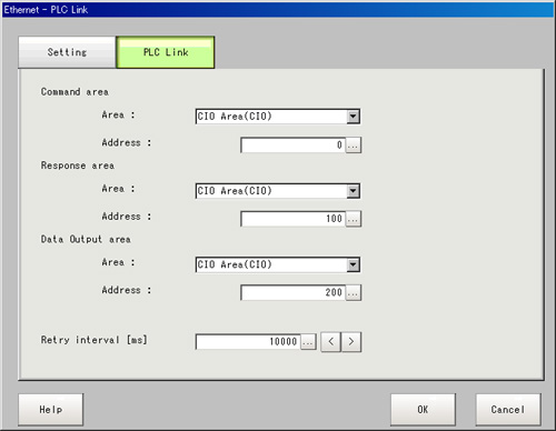
[9600]Set the port No. to use for data I/O with the controller. - Tap [PLC Link setting].The PLC Link Setting window is displayed.
- Set the following items.
 Setting itemSet value
[Factory default]DescriptionCommand areaArea- [CIO Area(CIO)]
- Work Area(WR)
- Holding Bit Area(HR)
- Auxiliary Bit Area(AR)
- DM Area (DM)
- EM Area(EMO)
Set the "Communication" area.Address0 to 99999
[0]Set the communication address.Response areaArea- [CIO Area(CIO)]
- Work Area(WR)
- Holding Bit Area(HR)
- Auxiliary Bit Area(AR)
- DM Area (DM)
- EM Area(EMO)
Set the "Communication" area.Address0 to 99999
[100]Set the communication address.Data output areaArea- [CIO Area(CIO)]
- Work Area(WR)
- Holding Bit Area(HR)
- Auxiliary Bit Area(AR)
- DM Area (DM)
- EM Area(EMO)
Set the "Communication" area.Address0 to 99999
[200]Set the communication address.Retry interval [ms]1000 to 999999
[10000]Set the communication retry interval. - Tap [OK].The settings are confirmed and the Ethernet window closes.
Checking Communication Status
Use PLC tools, etc. to check the communication status.