Measurement Parameters (Edge Positions)
This item specifies the judgement condition for measurement results.Measurement parameter can be changed as needed to address unstable measurement results.
- In the "Item tab" area, tap [Measurement].
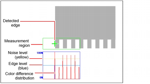
The edge profile of the measurement region is displayed as a graph in the "Image display" area.
 Note
Note- When the region is a circumference or arc, you can display the graph enlarged in the vertical direction.Place a check at "Zoom" and tap the button to adjust.
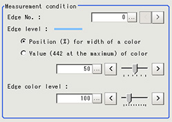
- If necessary, specify a value for each item in the "Measurement condition" area.
| Set value [factory default] | |
|---|
| | Specify the edge number used to extract edges. Edge numbers are assigned to detected edges starting from 0 and going on in the direction from the start point (the arrow point) to the end point (the direction of arrow) in the selected area. |
| - Position (%) for width of a color
- Value of color
| |
| | This emphasis level can be specified only if the edge color to detect is specified. |
| Set value [factory default] | |
|---|
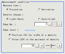
| | Select whether a black-to-white change or a white-to-black change should be recognized as a density change in the specified region. |
Measure type | [Projection]
Derivation | As the measurement type, specify either projection or derivation. |
| | Specify the edge number used to extract edges. Edge numbers are assigned to detected edges starting from 0 and going on in the direction from the start point (the arrow point) to the end point (the direction of arrow) in the selected area. |
| - Position (%) for width of a density
- Value of density
| |
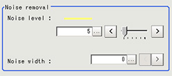
- If necessary, set each item in the "Noise removal" area.
| Set value [factory default] | |
|---|
| For color cameras:
0 to 442 [5] For monochrome cameras:
0 to 255 [5] | When edges are incorrectly detected due to noise, increase this value. |
| | Set the width for judging noise. When detection is affected by noise, increase this value. |
- When the setting has been changed, tap [Measure] in the "Detail" area to verify whether measurements can be made correctly.
- Set up the judgement condition.
 Note
Note- The values beside each item are measurement results of the displayed image.Take these values into consideration to determine the upper and lower limits.
| | |
|---|
| -99999.9999 to 99999.9999 | Specify the range of X-axis shifting that is judged to be OK. |
| -99999.9999 to 99999.9999 | Specify the range of Y-axis shifting that is judged to be OK. |
 See "User's Manual", "Edge Detection Measurement"Measure type[Projection]
 See "User's Manual", "Edge Detection Measurement"
 Note
Note


