Measurement Parameters (Defects/Contamination)
This item specifies the judgement condition for measurement results.Measurement parameters can be changed as needed to address unstable measurement results or to increase the processing speed.
 Note
NoteDefect detection mechanism
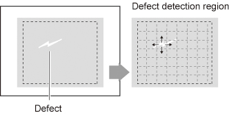
- After measurement region is drawn, a rectangle (defect detection region) is automatically formed in this region.While moving the defect detection region around, calculate the RGB color averages at each location and find the defect detection difference with surrounding defects. This difference is called the defect level. Calculate the defect level for all defect detection areas. If the maximum value exceeds the judgement value, it is judged that there are defects in the measurement region.
- In the "Item tab" area, tap [Measurement].
- Set the value of each item in the "Defect size" area.
| Set value [Factory default] | |
|---|
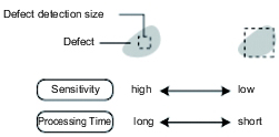
| | Specify the upper and lower limits of defect detection size based on the size of scratch or contamination to be detected.A defect detection region is automatically created with the number of pixels for the defects size. The larger the difference between upper and lower limits, the easier to detect defects/contamination of various sizes. For both upper and lower limits, higher values for defect detection size limits leads to weaker detection sensitivity and shorter processing time. |
- If necessary, set the value of each item in the "Measurement condition" area.
| Set value [Factory default] | |
|---|
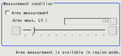
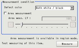
| | Place a check when you want to measure the size of defects.This item can divide the high defect detection regions into groups and output the surface and center of gravity coordinates of the group with the largest area. However, when only one region is specified with "Wide line", "Wide circle", or "Arc", area measurement is not possible. |
| | If you place a heck at Area Measurement, set defect level counted in the defect area. |
Detection object color (for monochrome cameras only) | | Select this value to detect defects that look darker than the background. |
| Select this value to detect defects that look lighter than the background. |
| Select this value when the brightness of defects is not known. |
 Note
Note- The comparison direction depends on the measurement region shapes and number.
For a rectangle, ellipse or polygon, comparison is with the defect detection regions above, below, left and right.This is called region inspection mode.
For a wide line, wide arc or wide circle, comparison is only with the two neighboring defect detection regions.
However, even for a wide line, wide arc or wide circle, when two or more figures are drawn, measurement is in region inspection mode.
- When the setting has been changed, tap [Measure] in the "Detail" area to verify whether measurements can be made correctly.
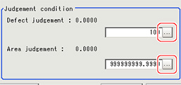
- Set up the judgement condition.
| Set value [Factory default] | |
|---|
| | Specify the upper limit for defect judgement. (The lower limit is fixed at 0.) When "30" is set, the OK value should be within the range of 0 to 30. |
| | Specify the maximum defect area. A_MAX: 307,200 for a 0.3-megapixel camera, 1,920,000 for a 2-megapixel camera |
 Note
Note- The value beside each item are measurement results of the displayed image.Take these values into consideration to determine the upper and lower limits.
 Note
Note