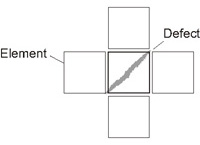
Measurement Parameters (High-precision Defects/Contamination Detection)
This item specifies the judgement condition for measurement results.Measurement parameters can be changed as needed to address unstable measurement results or to increase the processing speed.
- In the "Item tab" area, tap [Measurement].
- Set the detection parameters.
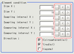 Setting itemSet value
[Factory default]Description4 to 64
[16]Specify the X-axis size of defects/contamination to be detected.The higher this value, the higher the degree of defects for large defects. Specify in units of pixels.Size Y4 to 64
[16]Specify the Y-axis size of defects/contamination to be detected.The higher this value, the higher the degree of defects for large defects.Specify in units of pixels.1 to 64
[2]Specify the interval for creating elements along the X axis.The smaller this value, the greater the defect detection performance, but the slower the processing speed.Specify in units of pixels.Sampling interval Y1 to 64
[2]Specify the interval for creating elements along the Y axis.The smaller this value, the greater the defect detection performance, but the slower the processing speed.Specify in units of pixels.1 to 32
[10]Set the number of neighboring elements compared with when the degree of defect is calculated,For example, if the Sampling interval X is set to 4 and the comparing interval X is set to 2, comparison is with separate elements of 4 x 2 = 8 pixels along the X axis.Comparing interval Y1 to 32
[10]Set the number of neighboring elements compared with when the degree of defect is calculated,For example, if the sampling interval Y is set to 4 and the comparing interval Y is set to 2, comparison is with separate elements of 4 x 2 = 8 pixels along the Y axis.- X(circumferential)
- Y(radial)
- Diagonal
Set the direction for detecting defects.
The smaller the direction setting count, the shorter the processing time. Note
Note- Measurement mode
In High-precision Defects/Contamination Detection measurement, the measurement mode depends on the number of registered region figures and their types.The way to make elements depends on the measurement mode. The relationship between the figure and measurement mode is as in the table below.Single figureMultiple figuresLineCircumferenceArcEllipseMinor axisPolygonMeasurement modeLineWide circle and arcWide circle and arcRegionRegionRegionRegionLine mode:- The direction parallel to the measurement region straight line is the X axis and the direction perpendicular is the Y axis.The shape of elements is rectangular. The element width and length are the number of pixels specified with the element size X and Y.
Wide circle and arc mode:- The circumferential direction along the measurement region wide circle (arc) is the X axis and the radial direction is the Y axis.The shape of elements is fan-shaped. If the circumference length of the wide circle (arc) of the measurement region is set to N, the element circumferential direction width is 360 degrees x the element size X / N. The element radial direction width is the number of pixels specified with the element size Y. The element circumferential direction width is defined as an angle, so the closer the element to the outer circumference, the larger the element.
Region mode:- The direction parallel to the measurement region is the X axis and the direction perpendicular is the Y axis.The shape of elements is rectangular.The element width and length are the number of pixels specified with the element size X and Y.
- If necessary, set the value of each item in the "Measurement condition" area.Value input method:
 See the "User's Manual", "Inputting Values"The "Area meas. LV" can be set also by dragging the slider or by tapping the buttons at the ends of the slider.For color cameras:
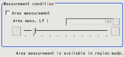 For monochrome cameras:
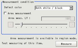 Setting itemSet value
[Factory default]DescriptionDetection object color
(for monochrome cameras only)BlackSelect this value when defects look blackish compared to the background.WhiteSelect this value when defects look whitish compared to the background.[Both white / black]Select this value when the brightness of defects is not known.Area measurement- Checked
- [Unchecked]
Place a check when you want to measure the size of defects.This item can divide the high defect detection regions into groups and output the surface and center of gravity coordinates of the group with the largest area.
However, when only one region is specified with "Wide line", "Wide circle", or "Arc", area measurement is not possible.0 to 999
[100]If you place a heck at Area Measurement, set defect level counted in the defect area. - When the setting has been changed, tap [Measure] in the "Detail" area to verify whether measurements can be made correctly.

- Set up the judgement condition.
 Setting itemSet value
[Factory default]DescriptionDefect judgement0 to 999
[100]Specify the upper limit for defect judgement. (The lower limit is fixed at 0.)
When "30" is set, the OK value should be within the range of 0 to 30.Area judgement0 to
[999999999.9999]Specify the maximum defect area.
A_MAX: 307,200 for a 0.3-megapixel camera, 1,920,000 for a 2-megapixel camera, 4,320,000 for a 5-megapixel camera - If necessary, set the display conditions for displayed images.
 Setting itemSet value
[Factory default]Description- [Checked]
- Unchecked
Set the profile display.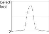 The maximum degree of defect along the X(circumferential) and Y(radial) is displayed with red lines.
If you tap in the measurement region on the image area, the profile in the XY directions from this point is displayed with yellow lines.- Checked
- [Unchecked]
Set the comparison element display.
Elements are created automatically during measurement.The density is calculated for each element and the position of defects/contamination is detected from the degree of their variation.